

loops meet each other to form a complete dislocation loop and a new line source
between the nodes. The process may then start again. This generation and
movement of dislocations is connected to plastic deformation. Acting Frank–
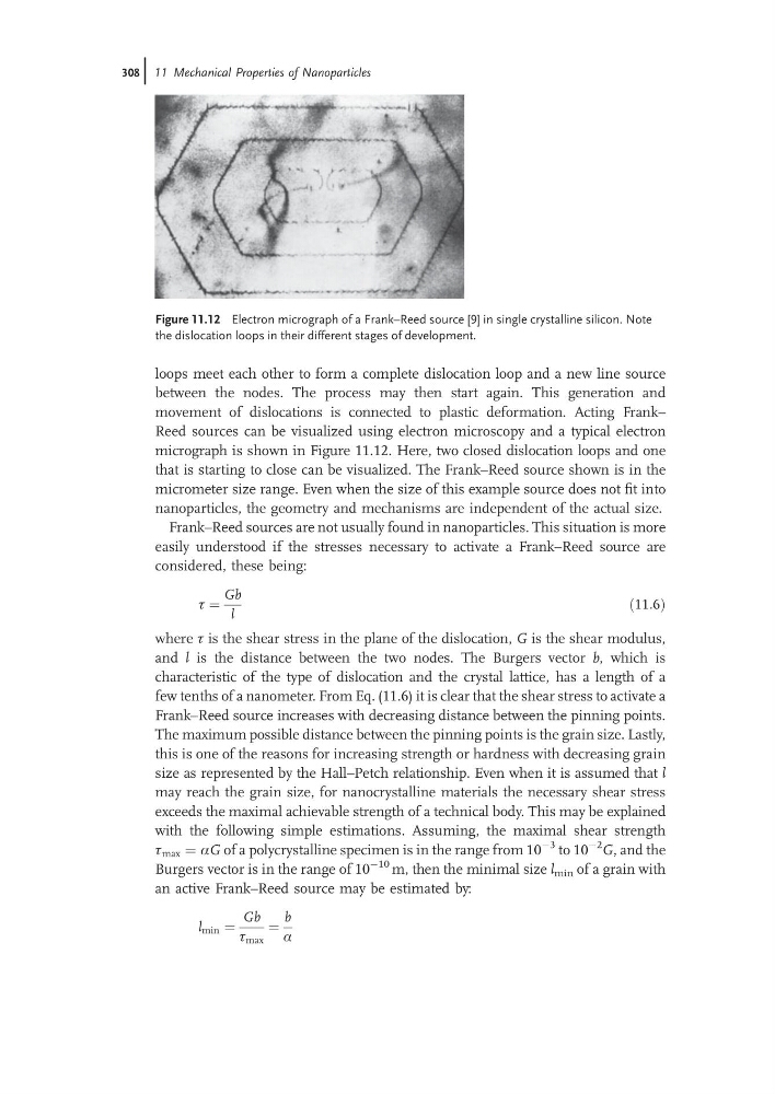
Reed sources can be visualized using electron microscopy and a typical electron
micrograph is shown in Figure 11.12. Here, two closed dislocation loops and one
that is starting to close can be visualized. The Frank–Reed source shown is in the
micrometer size range. Even when the size of this example source does not fit into
nanoparticles, the geometry and mechanisms are independent of the actual size.
Frank–Reed sources are not usually found in nanoparticles. This situation is more
easily understood if the stresses necessary to activate a Frank–Reed source are
considered, these being:
t ¼
Gb
l
ð11:6Þ
where t is the shear stress in the plane of the dislocation, G is the shear modulus,
and l is the distance between the two nodes. The Burgers vector b, which is
characteristic of the type of dislocation and the crystal lattice, has a length of a
few tenths of a nanometer. From Eq. (11.6) it is clear that the shear stress to activate a
Frank–Reed source increases with decreasing distance between the pinning points.
The maximum possible distance between the pinning points is the grain size. Lastly,
this is one of the reasons for increasing strength or hardness with decreasing grain
size as represented by the Hall–Petch relationship. Even when it is assumed that l
may reach the grain size, for nanocrystalline materials the necessary shear stress
exceeds the maximal achievable strength of a technical body. This may be explained
with the following simple estimations. Assuming, the maximal shear strength
t max ¼ aG of a polycrystalline specimen is in the range from 10
À3 to 10
À2 G, and the
Burgers vector is in the range of 10
À10 m, then the minimal size l min of a grain with
an active Frank–Reed source may be estimated by:
l min ¼
Gb
t max
¼
b
a
Figure 11.12 Electron micrograph of a Frank–Reed source [9] in single crystalline silicon. Note
the dislocation loops in their different stages of development.
308j 11 Mechanical Properties of Nanoparticles
between the nodes. The process may then start again. This generation and
movement of dislocations is connected to plastic deformation. Acting Frank–
Reed sources can be visualized using electron microscopy and a typical electron
micrograph is shown in Figure 11.12. Here, two closed dislocation loops and one
that is starting to close can be visualized. The Frank–Reed source shown is in the
micrometer size range. Even when the size of this example source does not fit into
nanoparticles, the geometry and mechanisms are independent of the actual size.
Frank–Reed sources are not usually found in nanoparticles. This situation is more
easily understood if the stresses necessary to activate a Frank–Reed source are
considered, these being:
t ¼
Gb
l
ð11:6Þ
where t is the shear stress in the plane of the dislocation, G is the shear modulus,
and l is the distance between the two nodes. The Burgers vector b, which is
characteristic of the type of dislocation and the crystal lattice, has a length of a
few tenths of a nanometer. From Eq. (11.6) it is clear that the shear stress to activate a
Frank–Reed source increases with decreasing distance between the pinning points.
The maximum possible distance between the pinning points is the grain size. Lastly,
this is one of the reasons for increasing strength or hardness with decreasing grain
size as represented by the Hall–Petch relationship. Even when it is assumed that l
may reach the grain size, for nanocrystalline materials the necessary shear stress
exceeds the maximal achievable strength of a technical body. This may be explained
with the following simple estimations. Assuming, the maximal shear strength
t max ¼ aG of a polycrystalline specimen is in the range from 10
À3 to 10
À2 G, and the
Burgers vector is in the range of 10
À10 m, then the minimal size l min of a grain with
an active Frank–Reed source may be estimated by:
l min ¼
Gb
t max
¼
b
a
Figure 11.12 Electron micrograph of a Frank–Reed source [9] in single crystalline silicon. Note
the dislocation loops in their different stages of development.
308j 11 Mechanical Properties of Nanoparticles