

13 nm. In order to estimate the actual field (in Tesla) at room temperature in Figure 6.7,
the numbers shown at the abscissa must be divided by approximately 100. In this way,
a clear characteristic of ferrofluids – that an extreme increase in viscosity occurs with
relatively small magnetic fields – becomes apparent.
As shown in Figure 6.7, a magnetic field, when held constant over time, leads to an
increase in the ferrofluid viscosity. However, the situation is more complex in an
alternating magnetic field, where one observes a positive contribution at low frequencies of the magnetic field and negative contribution at high frequencies. This is due to
rotatory oscillations of the particles, caused by the alternating magnetic field. As there
is no preference for any direction of rotation, in a first approximation, half of the
particles rotate clockwise and the other half counter-clockwise. Therefore, from a
macroscopic viewpoint, the angular velocity of the particles equals zero. However, any
vortex results in a nonzero angular velocity of the particles, which in turn leads to a
decrease in the effective viscosity; this is seen as a negative contribution to the viscosity.
6.3.3
Applications of Ferrofluids
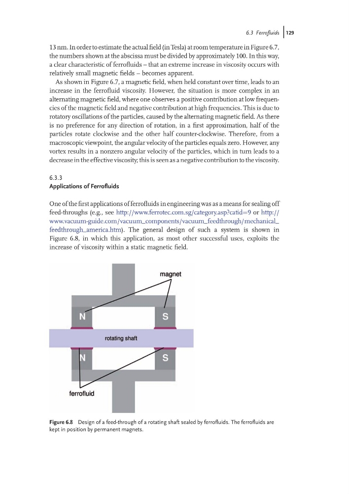
One of the first applications of ferrofluids in engineering was as a means for sealing off
feed-throughs (e.g., see http://www.ferrotec.com.sg/category.asp?catid¼9 or http://
www.vacuum-guide.com / vacuum_ components/ vacuum_ feedthrough/ mechanical_
feedthrough_america.htm). The general design of such a system is shown in
Figure 6.8, in which this application, as most other successful uses, exploits the
increase of viscosity within a static magnetic field.
Figure 6.8 Design of a feed-through of a rotating shaft sealed by ferrofluids. The ferrofluids are
kept in position by permanent magnets.
6.3 Ferrofluids j129
the numbers shown at the abscissa must be divided by approximately 100. In this way,
a clear characteristic of ferrofluids – that an extreme increase in viscosity occurs with
relatively small magnetic fields – becomes apparent.
As shown in Figure 6.7, a magnetic field, when held constant over time, leads to an
increase in the ferrofluid viscosity. However, the situation is more complex in an
alternating magnetic field, where one observes a positive contribution at low frequencies of the magnetic field and negative contribution at high frequencies. This is due to
rotatory oscillations of the particles, caused by the alternating magnetic field. As there
is no preference for any direction of rotation, in a first approximation, half of the
particles rotate clockwise and the other half counter-clockwise. Therefore, from a
macroscopic viewpoint, the angular velocity of the particles equals zero. However, any
vortex results in a nonzero angular velocity of the particles, which in turn leads to a
decrease in the effective viscosity; this is seen as a negative contribution to the viscosity.
6.3.3
Applications of Ferrofluids
One of the first applications of ferrofluids in engineering was as a means for sealing off
feed-throughs (e.g., see http://www.ferrotec.com.sg/category.asp?catid¼9 or http://
www.vacuum-guide.com / vacuum_ components/ vacuum_ feedthrough/ mechanical_
feedthrough_america.htm). The general design of such a system is shown in
Figure 6.8, in which this application, as most other successful uses, exploits the
increase of viscosity within a static magnetic field.
Figure 6.8 Design of a feed-through of a rotating shaft sealed by ferrofluids. The ferrofluids are
kept in position by permanent magnets.
6.3 Ferrofluids j129