

that the precursor molecules dissociate at the surface of the catalyst droplet. For
example, in order to obtain carbon nanotubes, CH 4 dissociates at the surface of an
iron or nickel droplet; the released carbon is then dissolved in the metal droplet and
the hydrogen leaves the system. At this stage, it is important to note that the selection
of catalysts is quite critical. To obtain carbon nanotubes, the process begins with a
solution of carbon in the catalyst metal particle. In order to avoid too-high
temperatures, it is advantageous to seek eutectic systems. After some time, the
material dissolved in the liquid catalyst reaches saturation and precipitates at the
surface of the properly selected substrate. There is no doubt that this process occurs
more rapidly if the catalyst particles are liquid, as solid-state diffusion is significantly
slower than diffusion in a liquid. Once the process has started, there is a steady
transport of dissociated material to the precipitate; the nucleus becomes larger and
the nanotube or nanorod grows. When considering a further process (e.g., to obtain
GaN nanorods), iron may be used as the catalyst. Both iron and gallium form a lowmelting phase with a melting point below 1200 K. Interestingly, the process
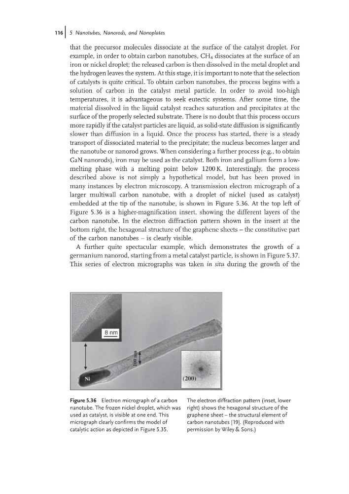
described above is not simply a hypothetical model, but has been proved in
many instances by electron microscopy. A transmission electron micrograph of a
larger multiwall carbon nanotube, with a droplet of nickel (used as catalyst)
embedded at the tip of the nanotube, is shown in Figure 5.36. At the top left of
Figure 5.36 is a higher-magnification insert, showing the different layers of the
carbon nanotube. In the electron diffraction pattern shown in the insert at the
bottom right, the hexagonal structure of the graphene sheets – the constitutive part
of the carbon nanotubes – is clearly visible.
A further quite spectacular example, which demonstrates the growth of a
germanium nanorod, starting from a metal catalyst particle, is shown in Figure 5.37.
This series of electron micrographs was taken in situ during the growth of the
Figure 5.36 Electron micrograph of a carbon
nanotube. The frozen nickel droplet, which was
used as catalyst, is visible at one end. This
micrograph clearly confirms the model of
catalytic action as depicted in Figure 5.35.
The electron diffraction pattern (inset, lower
right) shows the hexagonal structure of the
graphene sheet – the structural element of
carbon nanotubes [19]. (Reproduced with
permission by Wiley & Sons.)
116j 5 Nanotubes, Nanorods, and Nanoplates
example, in order to obtain carbon nanotubes, CH 4 dissociates at the surface of an
iron or nickel droplet; the released carbon is then dissolved in the metal droplet and
the hydrogen leaves the system. At this stage, it is important to note that the selection
of catalysts is quite critical. To obtain carbon nanotubes, the process begins with a
solution of carbon in the catalyst metal particle. In order to avoid too-high
temperatures, it is advantageous to seek eutectic systems. After some time, the
material dissolved in the liquid catalyst reaches saturation and precipitates at the
surface of the properly selected substrate. There is no doubt that this process occurs
more rapidly if the catalyst particles are liquid, as solid-state diffusion is significantly
slower than diffusion in a liquid. Once the process has started, there is a steady
transport of dissociated material to the precipitate; the nucleus becomes larger and
the nanotube or nanorod grows. When considering a further process (e.g., to obtain
GaN nanorods), iron may be used as the catalyst. Both iron and gallium form a lowmelting phase with a melting point below 1200 K. Interestingly, the process
described above is not simply a hypothetical model, but has been proved in
many instances by electron microscopy. A transmission electron micrograph of a
larger multiwall carbon nanotube, with a droplet of nickel (used as catalyst)
embedded at the tip of the nanotube, is shown in Figure 5.36. At the top left of
Figure 5.36 is a higher-magnification insert, showing the different layers of the
carbon nanotube. In the electron diffraction pattern shown in the insert at the
bottom right, the hexagonal structure of the graphene sheets – the constitutive part
of the carbon nanotubes – is clearly visible.
A further quite spectacular example, which demonstrates the growth of a
germanium nanorod, starting from a metal catalyst particle, is shown in Figure 5.37.
This series of electron micrographs was taken in situ during the growth of the
Figure 5.36 Electron micrograph of a carbon
nanotube. The frozen nickel droplet, which was
used as catalyst, is visible at one end. This
micrograph clearly confirms the model of
catalytic action as depicted in Figure 5.35.
The electron diffraction pattern (inset, lower
right) shows the hexagonal structure of the
graphene sheet – the structural element of
carbon nanotubes [19]. (Reproduced with
permission by Wiley & Sons.)
116j 5 Nanotubes, Nanorods, and Nanoplates