

From Eq. (2.2), we know that r M l ðtÞ ¼ R 0 þ vt þ R rotating ^ r 0 , bring it into Eq. (3.5)
and ignore the DC component, we can get
^ s b ðtÞ ¼
X L
l¼1
r M l ðtÞ
2
exp j2pf c
2 R 0 þ R rotating ^ r 0
À
Á
c
ð3:6Þ
Obviously, Eq. (3.6) in which time–frequency distribution can be obtained by
time–frequency analysis is the propeller echo signal which eliminates the echo of the
target body and translation. The time–frequency curve only includes the periodically
changing Micro-Doppler frequency, which is obviously caused by the rotating motion
of the propeller.
4 Simulation
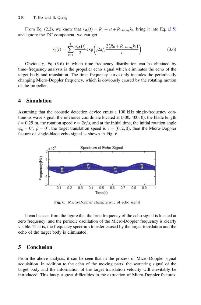
Assuming that the acoustic detection device emits a 100 kHz single-frequency continuous wave signal, the reference coordinate located at (300, 400, 0), the blade length
l = 0.25 m, the rotation speed r ¼ 2r=s, and at the initial time, the initial rotation angle
u 0 ¼ 0
, b ¼ 0
, the target translation speed is v ¼ ð0; 2; 0Þ, then the Micro-Doppler
feature of single-blade echo signal is shown in Fig. 6.
It can be seen from the figure that the base frequency of the echo signal is located at
zero frequency, and the periodic oscillation of the Micro-Doppler frequency is clearly
visible. That is, the frequency spectrum transfer caused by the target translation and the
echo of the target body is eliminated.
5 Conclusion
From the above analysis, it can be seen that in the process of Micro-Doppler signal
acquisition, in addition to the echo of the moving parts, the scattering signal of the
target body and the information of the target translation velocity will inevitably be
introduced. This has put great difficulties in the extraction of Micro-Doppler features.
Fig. 6. Micro-Doppler characteristic of echo signal
210
T. Bo and S. Qiang
and ignore the DC component, we can get
^ s b ðtÞ ¼
X L
l¼1
r M l ðtÞ
2
exp j2pf c
2 R 0 þ R rotating ^ r 0
À
Á
c
ð3:6Þ
Obviously, Eq. (3.6) in which time–frequency distribution can be obtained by
time–frequency analysis is the propeller echo signal which eliminates the echo of the
target body and translation. The time–frequency curve only includes the periodically
changing Micro-Doppler frequency, which is obviously caused by the rotating motion
of the propeller.
4 Simulation
Assuming that the acoustic detection device emits a 100 kHz single-frequency continuous wave signal, the reference coordinate located at (300, 400, 0), the blade length
l = 0.25 m, the rotation speed r ¼ 2r=s, and at the initial time, the initial rotation angle
u 0 ¼ 0
, b ¼ 0
, the target translation speed is v ¼ ð0; 2; 0Þ, then the Micro-Doppler
feature of single-blade echo signal is shown in Fig. 6.
It can be seen from the figure that the base frequency of the echo signal is located at
zero frequency, and the periodic oscillation of the Micro-Doppler frequency is clearly
visible. That is, the frequency spectrum transfer caused by the target translation and the
echo of the target body is eliminated.
5 Conclusion
From the above analysis, it can be seen that in the process of Micro-Doppler signal
acquisition, in addition to the echo of the moving parts, the scattering signal of the
target body and the information of the target translation velocity will inevitably be
introduced. This has put great difficulties in the extraction of Micro-Doppler features.
Fig. 6. Micro-Doppler characteristic of echo signal
210
T. Bo and S. Qiang