

s t ðtÞ ¼ expðj2pf c tÞ
ð 2:1Þ
Then, the echo signal of scattering point p received by the acoustic detection
equipment is
s r ðtÞ ¼ aexp j2pf c t À
rðtÞ
c
!
&
'
ð2:2Þ
where a is the amplitude of echo signal, c is the sound speed, rðtÞ ¼ R 0 þ vt þ R rotating ^ r 0
is the distance between the scattering point p and the acoustic detection equipment at
time t, where R 0 is the distance from the origin of the acoustic detection device to the
reference coordinate system, v is the target translational velocity, R rotating is the rotation
matrix in the reference coordinate system, and ^ r 0 is the initial vector of scattering point
p in the reference coordinate system [6].
For multiple scattering points, the total echo signal is
s r ðtÞ ¼
X N
i¼0
a i exp j2pf c t À
r i ðtÞ
c
!
&
'
ð2:3Þ
Assuming that the acoustic detection equipment emits a single-frequency continuous wave at a frequency of 600 kHz, the reference coordinate system is located
ðU ¼ 0; W ¼ 400
ffiffi ffi
2
p ; V ¼ 200Þ, then R 0 ¼ 0; 400
ffiffi ffi
2
p ; 200
À
Á T , and the initial Euler
angle is ð/ e ¼ 0
; h e ¼ 0
; u e ¼ 0
Þ, At the initial moment, the coordinates of the
propeller blade in the target local coordinate system are ½x 0 ¼ 0; y 0 ¼ 0; z ¼ ð0 $ 2Þ,
the angular velocity is x ¼ ðx x ¼ 8p; x y ¼ 0; x z ¼ 0Þ
T , and the target translational
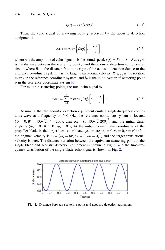
velocity is zero. The distance variation between the equivalent scattering point of the
single blade and acoustic detection equipment is shown in Fig. 1, and the time–frequency distribution of the single-blade echo signal is shown in Fig. 2.
Fig. 1. Distance between scattering point and acoustic detection equipment
206
T. Bo and S. Qiang
ð 2:1Þ
Then, the echo signal of scattering point p received by the acoustic detection
equipment is
s r ðtÞ ¼ aexp j2pf c t À
rðtÞ
c
!
&
'
ð2:2Þ
where a is the amplitude of echo signal, c is the sound speed, rðtÞ ¼ R 0 þ vt þ R rotating ^ r 0
is the distance between the scattering point p and the acoustic detection equipment at
time t, where R 0 is the distance from the origin of the acoustic detection device to the
reference coordinate system, v is the target translational velocity, R rotating is the rotation
matrix in the reference coordinate system, and ^ r 0 is the initial vector of scattering point
p in the reference coordinate system [6].
For multiple scattering points, the total echo signal is
s r ðtÞ ¼
X N
i¼0
a i exp j2pf c t À
r i ðtÞ
c
!
&
'
ð2:3Þ
Assuming that the acoustic detection equipment emits a single-frequency continuous wave at a frequency of 600 kHz, the reference coordinate system is located
ðU ¼ 0; W ¼ 400
ffiffi ffi
2
p ; V ¼ 200Þ, then R 0 ¼ 0; 400
ffiffi ffi
2
p ; 200
À
Á T , and the initial Euler
angle is ð/ e ¼ 0
; h e ¼ 0
; u e ¼ 0
Þ, At the initial moment, the coordinates of the
propeller blade in the target local coordinate system are ½x 0 ¼ 0; y 0 ¼ 0; z ¼ ð0 $ 2Þ,
the angular velocity is x ¼ ðx x ¼ 8p; x y ¼ 0; x z ¼ 0Þ
T , and the target translational
velocity is zero. The distance variation between the equivalent scattering point of the
single blade and acoustic detection equipment is shown in Fig. 1, and the time–frequency distribution of the single-blade echo signal is shown in Fig. 2.
Fig. 1. Distance between scattering point and acoustic detection equipment
206
T. Bo and S. Qiang