

5.8 Proportional Counter
67
B
A
C
F
D
E
Sample holder
through screw type
z
Y
K
cathode
H
Anode
Insulator
Mixed gas
G
To outside
after bubbling
through water
bubbler
M
M
L
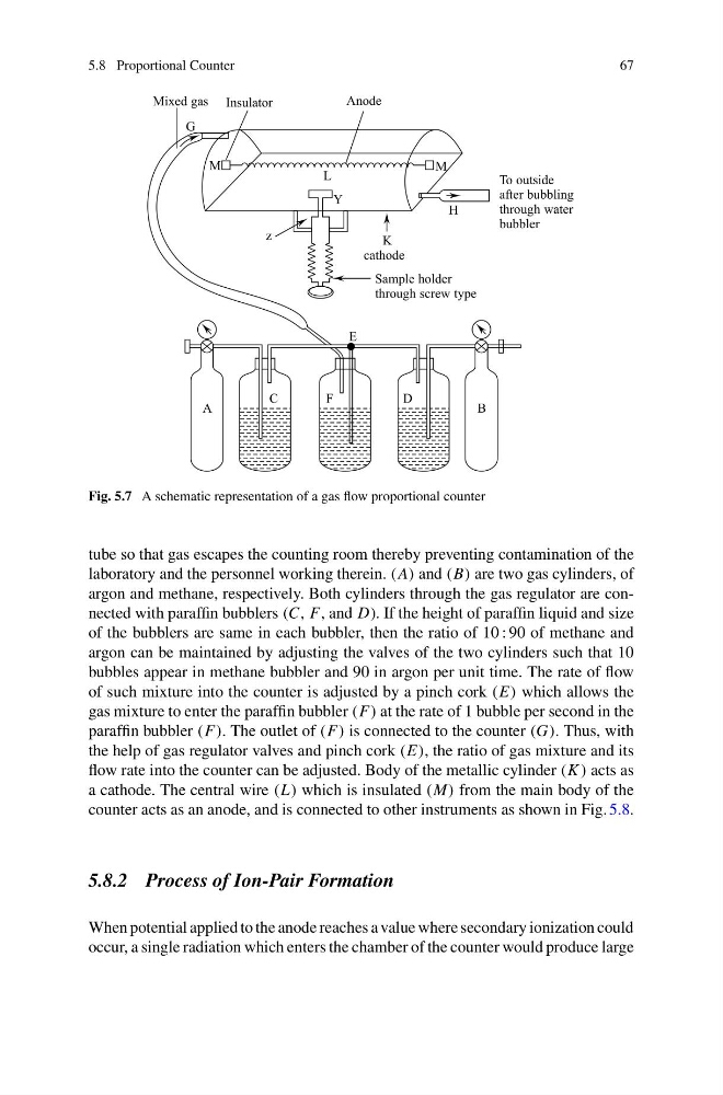
Fig. 5.7 A schematic representation of a gas flow proportional counter
tube so that gas escapes the counting room thereby preventing contamination of the
laboratory and the personnel working therein. (A) and (B) are two gas cylinders, of
argon and methane, respectively. Both cylinders through the gas regulator are connected with paraffin bubblers (C, F, and D). If the height of paraffin liquid and size
of the bubblers are same in each bubbler, then the ratio of 10 : 90 of methane and
argon can be maintained by adjusting the valves of the two cylinders such that 10
bubbles appear in methane bubbler and 90 in argon per unit time. The rate of flow
of such mixture into the counter is adjusted by a pinch cork (E) which allows the
gas mixture to enter the paraffin bubbler (F) at the rate of 1 bubble per second in the
paraffin bubbler (F). The outlet of (F) is connected to the counter (G). Thus, with
the help of gas regulator valves and pinch cork (E), the ratio of gas mixture and its
flow rate into the counter can be adjusted. Body of the metallic cylinder (K ) acts as
a cathode. The central wire (L) which is insulated (M) from the main body of the
counter acts as an anode, and is connected to other instruments as shown in Fig. 5.8.
5.8.2 Process of Ion-Pair Formation
When potential applied to the anode reaches a value where secondary ionization could
occur, a single radiation which enters the chamber of the counter would produce large
67
B
A
C
F
D
E
Sample holder
through screw type
z
Y
K
cathode
H
Anode
Insulator
Mixed gas
G
To outside
after bubbling
through water
bubbler
M
M
L
Fig. 5.7 A schematic representation of a gas flow proportional counter
tube so that gas escapes the counting room thereby preventing contamination of the
laboratory and the personnel working therein. (A) and (B) are two gas cylinders, of
argon and methane, respectively. Both cylinders through the gas regulator are connected with paraffin bubblers (C, F, and D). If the height of paraffin liquid and size
of the bubblers are same in each bubbler, then the ratio of 10 : 90 of methane and
argon can be maintained by adjusting the valves of the two cylinders such that 10
bubbles appear in methane bubbler and 90 in argon per unit time. The rate of flow
of such mixture into the counter is adjusted by a pinch cork (E) which allows the
gas mixture to enter the paraffin bubbler (F) at the rate of 1 bubble per second in the
paraffin bubbler (F). The outlet of (F) is connected to the counter (G). Thus, with
the help of gas regulator valves and pinch cork (E), the ratio of gas mixture and its
flow rate into the counter can be adjusted. Body of the metallic cylinder (K ) acts as
a cathode. The central wire (L) which is insulated (M) from the main body of the
counter acts as an anode, and is connected to other instruments as shown in Fig. 5.8.
5.8.2 Process of Ion-Pair Formation
When potential applied to the anode reaches a value where secondary ionization could
occur, a single radiation which enters the chamber of the counter would produce large