

5.3 General Design of an Ionization Chamber
55
Insulator
(y)
e
+
Radioactive
sample
Window (x)
Ion Pair
V
R
Voltmeter
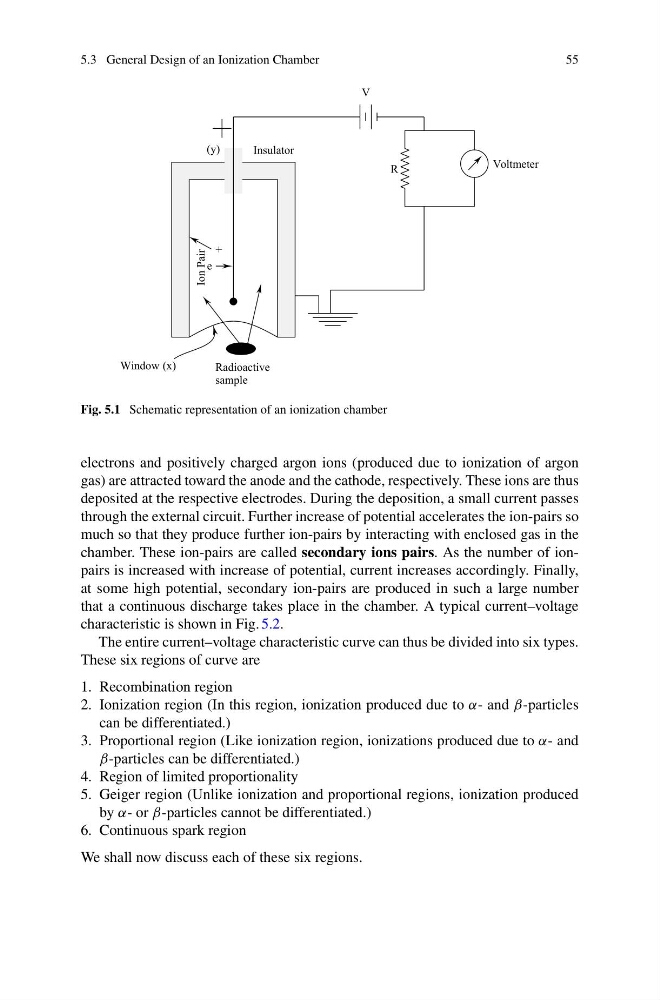
Fig. 5.1 Schematic representation of an ionization chamber
electrons and positively charged argon ions (produced due to ionization of argon
gas) are attracted toward the anode and the cathode, respectively. These ions are thus
deposited at the respective electrodes. During the deposition, a small current passes
through the external circuit. Further increase of potential accelerates the ion-pairs so
much so that they produce further ion-pairs by interacting with enclosed gas in the
chamber. These ion-pairs are called secondary ions pairs. As the number of ionpairs is increased with increase of potential, current increases accordingly. Finally,
at some high potential, secondary ion-pairs are produced in such a large number
that a continuous discharge takes place in the chamber. A typical current–voltage
characteristic is shown in Fig. 5.2.
The entire current–voltage characteristic curve can thus be divided into six types.
These six regions of curve are
1. Recombination region
2. Ionization region (In this region, ionization produced due to α- and β-particles
can be differentiated.)
3. Proportional region (Like ionization region, ionizations produced due to α- and
β-particles can be differentiated.)
4. Region of limited proportionality
5. Geiger region (Unlike ionization and proportional regions, ionization produced
by α- or β-particles cannot be differentiated.)
6. Continuous spark region
We shall now discuss each of these six regions.
55
Insulator
(y)
e
+
Radioactive
sample
Window (x)
Ion Pair
V
R
Voltmeter
Fig. 5.1 Schematic representation of an ionization chamber
electrons and positively charged argon ions (produced due to ionization of argon
gas) are attracted toward the anode and the cathode, respectively. These ions are thus
deposited at the respective electrodes. During the deposition, a small current passes
through the external circuit. Further increase of potential accelerates the ion-pairs so
much so that they produce further ion-pairs by interacting with enclosed gas in the
chamber. These ion-pairs are called secondary ions pairs. As the number of ionpairs is increased with increase of potential, current increases accordingly. Finally,
at some high potential, secondary ion-pairs are produced in such a large number
that a continuous discharge takes place in the chamber. A typical current–voltage
characteristic is shown in Fig. 5.2.
The entire current–voltage characteristic curve can thus be divided into six types.
These six regions of curve are
1. Recombination region
2. Ionization region (In this region, ionization produced due to α- and β-particles
can be differentiated.)
3. Proportional region (Like ionization region, ionizations produced due to α- and
β-particles can be differentiated.)
4. Region of limited proportionality
5. Geiger region (Unlike ionization and proportional regions, ionization produced
by α- or β-particles cannot be differentiated.)
6. Continuous spark region
We shall now discuss each of these six regions.