

100
6 Scintillation Counter
6.6.1 Inorganic Scintillator
Inorganic scintillator are high density materials. Probability of interaction of γ -rays
with phosphor increases in the presence of high density material. Therefore, inorganic
scintillators are generally iodide salts of alkali metals as iodine atoms are the largest
anions offering a large area for stopping γ -rays. Thallium ion is used as a dopant in
these crystals because it has the property to shift the wavelength of the photon into
the visible region. The most common scintillator is NaI(Tl), but CsI(Tl) is also used
in some special cases (Table 6.1).
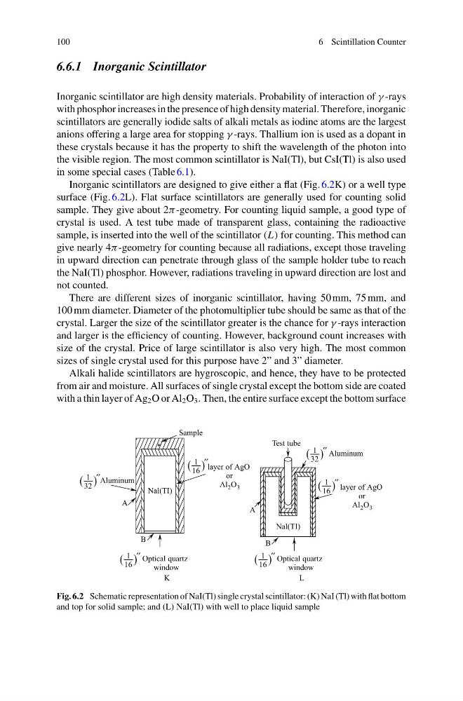
Inorganic scintillators are designed to give either a flat (Fig. 6.2K) or a well type
surface (Fig. 6.2L). Flat surface scintillators are generally used for counting solid
sample. They give about 2π -geometry. For counting liquid sample, a good type of
crystal is used. A test tube made of transparent glass, containing the radioactive
sample, is inserted into the well of the scintillator (L) for counting. This method can
give nearly 4π -geometry for counting because all radiations, except those traveling
in upward direction can penetrate through glass of the sample holder tube to reach
the NaI(Tl) phosphor. However, radiations traveling in upward direction are lost and
not counted.
There are different sizes of inorganic scintillator, having 50 mm, 75 mm, and
100 mm diameter. Diameter of the photomultiplier tube should be same as that of the
crystal. Larger the size of the scintillator greater is the chance for γ -rays interaction
and larger is the efficiency of counting. However, background count increases with
size of the crystal. Price of large scintillator is also very high. The most common
sizes of single crystal used for this purpose have 2” and 3” diameter.
Alkali halide scintillators are hygroscopic, and hence, they have to be protected
from air and moisture. All surfaces of single crystal except the bottom side are coated
with a thin layer of Ag 2 O or Al 2 O 3 . Then, the entire surface except the bottom surface
Fig. 6.2 Schematic representation of NaI(Tl) single crystal scintillator: (K) NaI (Tl) with flat bottom
and top for solid sample; and (L) NaI(Tl) with well to place liquid sample
6 Scintillation Counter
6.6.1 Inorganic Scintillator
Inorganic scintillator are high density materials. Probability of interaction of γ -rays
with phosphor increases in the presence of high density material. Therefore, inorganic
scintillators are generally iodide salts of alkali metals as iodine atoms are the largest
anions offering a large area for stopping γ -rays. Thallium ion is used as a dopant in
these crystals because it has the property to shift the wavelength of the photon into
the visible region. The most common scintillator is NaI(Tl), but CsI(Tl) is also used
in some special cases (Table 6.1).
Inorganic scintillators are designed to give either a flat (Fig. 6.2K) or a well type
surface (Fig. 6.2L). Flat surface scintillators are generally used for counting solid
sample. They give about 2π -geometry. For counting liquid sample, a good type of
crystal is used. A test tube made of transparent glass, containing the radioactive
sample, is inserted into the well of the scintillator (L) for counting. This method can
give nearly 4π -geometry for counting because all radiations, except those traveling
in upward direction can penetrate through glass of the sample holder tube to reach
the NaI(Tl) phosphor. However, radiations traveling in upward direction are lost and
not counted.
There are different sizes of inorganic scintillator, having 50 mm, 75 mm, and
100 mm diameter. Diameter of the photomultiplier tube should be same as that of the
crystal. Larger the size of the scintillator greater is the chance for γ -rays interaction
and larger is the efficiency of counting. However, background count increases with
size of the crystal. Price of large scintillator is also very high. The most common
sizes of single crystal used for this purpose have 2” and 3” diameter.
Alkali halide scintillators are hygroscopic, and hence, they have to be protected
from air and moisture. All surfaces of single crystal except the bottom side are coated
with a thin layer of Ag 2 O or Al 2 O 3 . Then, the entire surface except the bottom surface
Fig. 6.2 Schematic representation of NaI(Tl) single crystal scintillator: (K) NaI (Tl) with flat bottom
and top for solid sample; and (L) NaI(Tl) with well to place liquid sample