

8
P. K. Shen
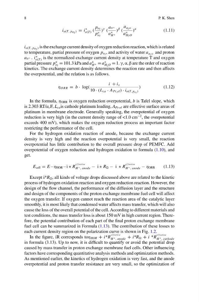
i o(T, p O 2 ) = i
∗
o(T ) (
p o 2
p ∗
o 2
)
γ
(
aH+
a
∗
H +
)
β
(
a H 2 O
a
∗
H 2 O
)
a
(1.11)
i o(T, p O 2 ) is the exchange current density of oxygen reduction reaction, which is related
to temperature, partial pressure of oxygen p o 2 , and activity of water a H 2 O and proton
aH+ . i
∗
o(T ) is the normalized exchange current density at temperature T and oxygen
partial pressure p
∗
o 2
= 101.3 kPa and a
∗
H + = a
∗
H 2 O = 1. γ, α, β are the order of reaction
kinetics. The exchange current density determines the reaction rate and then affects
the overpotential, and the relation is as follows.
η O R R = b · log(
i + i x
10 · (L ca · A Pt,el ) · i o(T, p o 2 )
)
(1.12)
In the formula, η ORR is oxygen reduction overpotential, b is Tafel slope, which
is 2.303 RT/a c F, L ca is cathode platinum loading, A Pt , el are effective surface areas of
platinum in membrane electrode. Generally speaking, the overpotential of oxygen
reduction is very high (in the current density range of <1.0 cm
−2 , the overpotential
exceeds 400 mV), which makes the oxygen reduction process an important factor
restricting the performance of the cell.
For the hydrogen oxidation reaction of anode, because the exchange current
density is very high and the reaction overpotential is very small, the reaction
overpotential has little contribution to the overall pressure drop of PEMFC. Add
overpotential of oxygen reduction and hydrogen oxidation to formula (1.10), and
get.
E cell = E−η HOR −i ∗ R
e f f ective
H + , anode − i ∗ R − i ∗ R
e f f ective
H + , anode − η ORR
(1.13)
Except i*R , all kinds of voltage drops discussed above are related to the kinetic
process of hydrogen oxidation reaction and oxygen reduction reaction. However, the
design of the flow channel, the performance of the diffusion layer and the structure
and design of the components of the proton exchange membrane fuel cell will affect
the oxygen transfer. If oxygen cannot reach the reaction area of the catalytic layer
smoothly, it is most likely that condensed water affects mass transfer, which will also
cause the loss of the overall potential of the cell. According to different materials and
test conditions, the mass transfer loss is about 150 mV in high current region. Therefore, the potential contribution of each part of the final proton exchange membrane
fuel cell can be summarized in Formula (1.13). The contribution of these losses to
each current density region on the polarization curve is shown in Fig. 1.2.
In the figure, iR corresponds toη HOR + i* R
e f f ective
H + , anode + i*R + i *R
e f f ective
H + , cathode
in formula (3.13). Up to now, it is difficult to quantify or avoid the potential drop
caused by mass transfer in proton exchange membrane fuel cells. Other influencing
factors have corresponding quantitative analysis methods and optimization methods.
As mentioned earlier, the kinetics of hydrogen oxidation is very fast, and the anode
overpotential and proton transfer resistance are very small, so the optimization of
P. K. Shen
i o(T, p O 2 ) = i
∗
o(T ) (
p o 2
p ∗
o 2
)
γ
(
aH+
a
∗
H +
)
β
(
a H 2 O
a
∗
H 2 O
)
a
(1.11)
i o(T, p O 2 ) is the exchange current density of oxygen reduction reaction, which is related
to temperature, partial pressure of oxygen p o 2 , and activity of water a H 2 O and proton
aH+ . i
∗
o(T ) is the normalized exchange current density at temperature T and oxygen
partial pressure p
∗
o 2
= 101.3 kPa and a
∗
H + = a
∗
H 2 O = 1. γ, α, β are the order of reaction
kinetics. The exchange current density determines the reaction rate and then affects
the overpotential, and the relation is as follows.
η O R R = b · log(
i + i x
10 · (L ca · A Pt,el ) · i o(T, p o 2 )
)
(1.12)
In the formula, η ORR is oxygen reduction overpotential, b is Tafel slope, which
is 2.303 RT/a c F, L ca is cathode platinum loading, A Pt , el are effective surface areas of
platinum in membrane electrode. Generally speaking, the overpotential of oxygen
reduction is very high (in the current density range of <1.0 cm
−2 , the overpotential
exceeds 400 mV), which makes the oxygen reduction process an important factor
restricting the performance of the cell.
For the hydrogen oxidation reaction of anode, because the exchange current
density is very high and the reaction overpotential is very small, the reaction
overpotential has little contribution to the overall pressure drop of PEMFC. Add
overpotential of oxygen reduction and hydrogen oxidation to formula (1.10), and
get.
E cell = E−η HOR −i ∗ R
e f f ective
H + , anode − i ∗ R − i ∗ R
e f f ective
H + , anode − η ORR
(1.13)
Except i*R , all kinds of voltage drops discussed above are related to the kinetic
process of hydrogen oxidation reaction and oxygen reduction reaction. However, the
design of the flow channel, the performance of the diffusion layer and the structure
and design of the components of the proton exchange membrane fuel cell will affect
the oxygen transfer. If oxygen cannot reach the reaction area of the catalytic layer
smoothly, it is most likely that condensed water affects mass transfer, which will also
cause the loss of the overall potential of the cell. According to different materials and
test conditions, the mass transfer loss is about 150 mV in high current region. Therefore, the potential contribution of each part of the final proton exchange membrane
fuel cell can be summarized in Formula (1.13). The contribution of these losses to
each current density region on the polarization curve is shown in Fig. 1.2.
In the figure, iR corresponds toη HOR + i* R
e f f ective
H + , anode + i*R + i *R
e f f ective
H + , cathode
in formula (3.13). Up to now, it is difficult to quantify or avoid the potential drop
caused by mass transfer in proton exchange membrane fuel cells. Other influencing
factors have corresponding quantitative analysis methods and optimization methods.
As mentioned earlier, the kinetics of hydrogen oxidation is very fast, and the anode
overpotential and proton transfer resistance are very small, so the optimization of