

9 Mössbauer Spectroscopic Studies on Atomic Diffusion in Materials
491
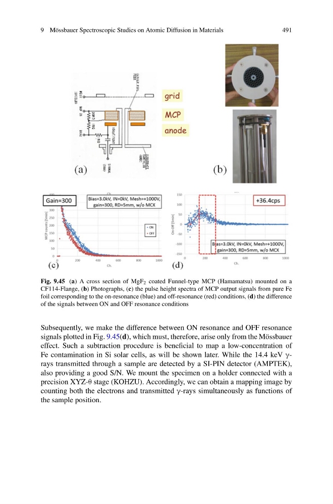
Fig. 9.45 (a) A cross section of MgF 2 coated Funnel-type MCP (Hamamatsu) mounted on a
CF114-Flange, (b) Photographs, (c) the pulse height spectra of MCP output signals from pure Fe
foil corresponding to the on-resonance (blue) and off-resonance (red) conditions, (d) the difference
of the signals between ON and OFF resonance conditions
Subsequently, we make the difference between ON resonance and OFF resonance
signals plotted in Fig. 9.45(d), which must, therefore, arise only from the Mössbauer
effect. Such a subtraction procedure is beneficial to map a low-concentration of
Fe contamination in Si solar cells, as will be shown later. While the 14.4 keV γrays transmitted through a sample are detected by a SI-PIN detector (AMPTEK),
also providing a good S/N. We mount the specimen on a holder connected with a
precision XYZ-θ stage (KOHZU). Accordingly, we can obtain a mapping image by
counting both the electrons and transmitted γ-rays simultaneously as functions of
the sample position.
491
Fig. 9.45 (a) A cross section of MgF 2 coated Funnel-type MCP (Hamamatsu) mounted on a
CF114-Flange, (b) Photographs, (c) the pulse height spectra of MCP output signals from pure Fe
foil corresponding to the on-resonance (blue) and off-resonance (red) conditions, (d) the difference
of the signals between ON and OFF resonance conditions
Subsequently, we make the difference between ON resonance and OFF resonance
signals plotted in Fig. 9.45(d), which must, therefore, arise only from the Mössbauer
effect. Such a subtraction procedure is beneficial to map a low-concentration of
Fe contamination in Si solar cells, as will be shown later. While the 14.4 keV γrays transmitted through a sample are detected by a SI-PIN detector (AMPTEK),
also providing a good S/N. We mount the specimen on a holder connected with a
precision XYZ-θ stage (KOHZU). Accordingly, we can obtain a mapping image by
counting both the electrons and transmitted γ-rays simultaneously as functions of
the sample position.