

490
Y. Yoshida
with/without the MCX lens: (a) without MCX lens, i.e., we collimated the γ-rays
only through a pin-hole of a lead plate with a diameter of 2 mmφ, (b) with different
MCX lens of spot size of 250 μmφ and a focus length 100 mm, and (c) 75 μmφ and
50 mm, respectively. It is evident in Fig. 9.43 that the absorption area decreases with
decreasing the spot sizes, affecting the S/N for the Mössbauer-effect image contrast
seriously. This tendency appears to be because the number of total reflections inside
the capillary channels must increase with decreasing the spot size. Since we use the
“total reflections” of the γ-rays inside of the capillaries with a diameter of 5 μmφ,
there must exist an energy loss during the focusing process by the MCX lens. For
observing the Mössbauer effect, the energy loss must be less than 10
–9 eV, which
is entirely different from the case for X-ray micro-beam analysis. Conclusively, we
can use this focusing technique for mapping an image by selecting the resonance
condition on a spectral component. The spatial resolution can reach about 10 μm by
overlapping the mapping points, as will be shown in the examples.
Finally, the third essential technique is the noise-free detection system for the
transmitted γ-rays and the electrons after the Mössbauer resonant absorption of
14.4 keV γ-beams. Therefore, we must carefully consider the measuring geometry
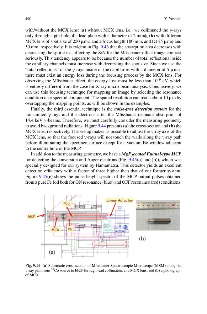
to avoid background radiations. Figure 9.44 presents (a) the cross-section and (b) the
MCX lens, respectively. The set-up makes us possible to adjust the γ-ray axis of the
MCX lens, so that the focused γ-rays will not touch the walls along the γ-ray path
before illuminating the specimen surface except for a vacuum Be-window adjacent
to the centre hole of the MCP.
In addition to the measuring geometry, we have a MgF 2 coated Funnel-type MCP
for detecting the conversion and Auger electrons (Fig. 9.45(a) and (b)), which was
specially designed for our system by Hamamatsu. This detector yields an excellent
detection efficiency with a factor of three higher than that of our former system.
Figure 9.45(c) shows the pulse height spectra of the MCP output pulses obtained
from a pure Fe foil both for ON resonance (blue) and OFF resonance (red) conditions.
Fig. 9.44 (a) Schematic cross section of Mössbauer Spectroscopic Microscope (MSM) along the
γ-ray path from 57 Co source to MCP through lead collimators and MCX lens, and (b) a photograph
of MCX
Y. Yoshida
with/without the MCX lens: (a) without MCX lens, i.e., we collimated the γ-rays
only through a pin-hole of a lead plate with a diameter of 2 mmφ, (b) with different
MCX lens of spot size of 250 μmφ and a focus length 100 mm, and (c) 75 μmφ and
50 mm, respectively. It is evident in Fig. 9.43 that the absorption area decreases with
decreasing the spot sizes, affecting the S/N for the Mössbauer-effect image contrast
seriously. This tendency appears to be because the number of total reflections inside
the capillary channels must increase with decreasing the spot size. Since we use the
“total reflections” of the γ-rays inside of the capillaries with a diameter of 5 μmφ,
there must exist an energy loss during the focusing process by the MCX lens. For
observing the Mössbauer effect, the energy loss must be less than 10
–9 eV, which
is entirely different from the case for X-ray micro-beam analysis. Conclusively, we
can use this focusing technique for mapping an image by selecting the resonance
condition on a spectral component. The spatial resolution can reach about 10 μm by
overlapping the mapping points, as will be shown in the examples.
Finally, the third essential technique is the noise-free detection system for the
transmitted γ-rays and the electrons after the Mössbauer resonant absorption of
14.4 keV γ-beams. Therefore, we must carefully consider the measuring geometry
to avoid background radiations. Figure 9.44 presents (a) the cross-section and (b) the
MCX lens, respectively. The set-up makes us possible to adjust the γ-ray axis of the
MCX lens, so that the focused γ-rays will not touch the walls along the γ-ray path
before illuminating the specimen surface except for a vacuum Be-window adjacent
to the centre hole of the MCP.
In addition to the measuring geometry, we have a MgF 2 coated Funnel-type MCP
for detecting the conversion and Auger electrons (Fig. 9.45(a) and (b)), which was
specially designed for our system by Hamamatsu. This detector yields an excellent
detection efficiency with a factor of three higher than that of our former system.
Figure 9.45(c) shows the pulse height spectra of the MCP output pulses obtained
from a pure Fe foil both for ON resonance (blue) and OFF resonance (red) conditions.
Fig. 9.44 (a) Schematic cross section of Mössbauer Spectroscopic Microscope (MSM) along the
γ-ray path from 57 Co source to MCP through lead collimators and MCX lens, and (b) a photograph
of MCX