

156
R. Röhlsberger and J. Evers
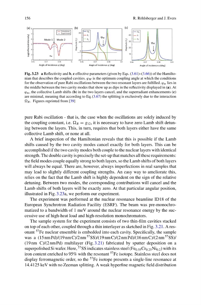
Fig. 3.23 a Reflectivity and b, c effective parameters (given by Eqs. (3.61)–(3.66)) of the Hamiltonian that describes the coupled cavities. ϕ M is the optimum coupling angle at which the conditions
for the observation of pure Rabi oscillations between the two resonant layers are fulfilled. ϕ m lies in
the middle between the two cavity modes that show up as dips in the reflectivity displayed in (a). At
ϕ m , the collective Lamb shifts (b) in the two layers cancel, and the superradiant enhancements (c)
are minimal, meaning that according to Eq. (3.67) the splitting is exclusively due to the interaction
R . Figures reprinted from [39]
pure Rabi oscillation - that is, the case when the oscillations are solely induced by
the coupling constant, i.e. R = g 12 , it is necessary to have zero Lamb shift detuning between the layers. This, in turn, requires that both layers either have the same
collective Lamb shift, or none at all.
A brief inspection of the Hamiltonian reveals that this is possible if the Lamb
shifts caused by the two cavity modes cancel exactly for both layers. This can be
accomplished if the two cavity modes both couple to the nuclear layers with identical
strength. The double cavity is precisely the set-up that matches all these requirements:
the field modes couple equally strong to both layers, so the Lamb shifts of both layers
will always be equal. There are, however, always imperfections in real samples that
may lead to slightly different coupling strengths. An easy way to ameliorate this,
relies on the fact that the Lamb shift is highly dependent on the sign of the relative
detuning. Between two modes, the corresponding contributions will cancel and the
Lamb shifts of both layers will be exactly zero. At that particular angular position,
illustrated in Fig. 3.23a, we perform our experiment.
The experiment was performed at the nuclear resonance beamline ID18 of the
European Synchrotron Radiation Facility (ESRF). The beam was pre-monochromatized to a bandwidth of 1 meV around the nuclear resonance energy by the successive use of high-heat load and high-resolution monochromators.
The sample system for the experiment consists of two thin-film cavities stacked
on top of each other, coupled through a thin interlayer as sketched in Fig. 3.21. A resonant
57 Fe nuclear ensemble is embedded into each cavity. Specifically, the sample
was a (15 nm Pd)/(19 nm C)/2 nm
57 SS)/(19 nm C)/(2 nm Pd)/(16 nm C)/(2 nm
57 SS)/
(19 nm C)/(2 nm Pd) multilayer (Fig. 3.21) fabricated by sputter deposition on a
superpolished Si wafer. Here,
57 SS indicates stainless steel (Fe 0.55 Cr 0.25 Ni 0.2 ) with its
iron content enriched to 95% with the resonant
57 Fe isotope. Stainless steel does not
display ferromagnetic order, so the
57 Fe isotope presents a single-line resonance at
14.4125 keV with no Zeeman splitting. A weak hyperfine magnetic field distribution
R. Röhlsberger and J. Evers
Fig. 3.23 a Reflectivity and b, c effective parameters (given by Eqs. (3.61)–(3.66)) of the Hamiltonian that describes the coupled cavities. ϕ M is the optimum coupling angle at which the conditions
for the observation of pure Rabi oscillations between the two resonant layers are fulfilled. ϕ m lies in
the middle between the two cavity modes that show up as dips in the reflectivity displayed in (a). At
ϕ m , the collective Lamb shifts (b) in the two layers cancel, and the superradiant enhancements (c)
are minimal, meaning that according to Eq. (3.67) the splitting is exclusively due to the interaction
R . Figures reprinted from [39]
pure Rabi oscillation - that is, the case when the oscillations are solely induced by
the coupling constant, i.e. R = g 12 , it is necessary to have zero Lamb shift detuning between the layers. This, in turn, requires that both layers either have the same
collective Lamb shift, or none at all.
A brief inspection of the Hamiltonian reveals that this is possible if the Lamb
shifts caused by the two cavity modes cancel exactly for both layers. This can be
accomplished if the two cavity modes both couple to the nuclear layers with identical
strength. The double cavity is precisely the set-up that matches all these requirements:
the field modes couple equally strong to both layers, so the Lamb shifts of both layers
will always be equal. There are, however, always imperfections in real samples that
may lead to slightly different coupling strengths. An easy way to ameliorate this,
relies on the fact that the Lamb shift is highly dependent on the sign of the relative
detuning. Between two modes, the corresponding contributions will cancel and the
Lamb shifts of both layers will be exactly zero. At that particular angular position,
illustrated in Fig. 3.23a, we perform our experiment.
The experiment was performed at the nuclear resonance beamline ID18 of the
European Synchrotron Radiation Facility (ESRF). The beam was pre-monochromatized to a bandwidth of 1 meV around the nuclear resonance energy by the successive use of high-heat load and high-resolution monochromators.
The sample system for the experiment consists of two thin-film cavities stacked
on top of each other, coupled through a thin interlayer as sketched in Fig. 3.21. A resonant
57 Fe nuclear ensemble is embedded into each cavity. Specifically, the sample
was a (15 nm Pd)/(19 nm C)/2 nm
57 SS)/(19 nm C)/(2 nm Pd)/(16 nm C)/(2 nm
57 SS)/
(19 nm C)/(2 nm Pd) multilayer (Fig. 3.21) fabricated by sputter deposition on a
superpolished Si wafer. Here,
57 SS indicates stainless steel (Fe 0.55 Cr 0.25 Ni 0.2 ) with its
iron content enriched to 95% with the resonant
57 Fe isotope. Stainless steel does not
display ferromagnetic order, so the
57 Fe isotope presents a single-line resonance at
14.4125 keV with no Zeeman splitting. A weak hyperfine magnetic field distribution