

66
T. T. Bui and S. Nakata
At the channel bottom, we are enforced a no-slip condition through several layers
of ghost particles. The objective of the simulation is to verify the velocity field of fluid
particles throughout the simulation and compare with the analytical solution in Eq. (9).
The simulation is carried out for a long enough time in order to check the stability
of the fluid flow. The particles are initially distributed with a resolution 4x = 4h/125
with 2000 particles and applied for Re = 10,100 and 200, respectively.
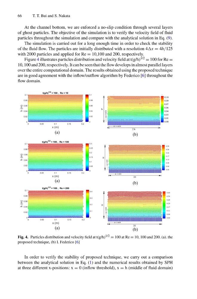
Figure 4 illustrates particles distribution and velocity field at t(g/h) 1/2 = 100 for Re =
10, 100 and 200, respectively. It can be seen that the flow develops in almost parallel layers
over the entire computational domain. The results obtained using the proposed technique
are in good agreement with the inflow/outflow algorithm by Federico [6] throughout the
flow domain.
(a)
(b)
(a)
(b)
(a)
(b)
Fig. 4. Particles distribution and velocity field at t(g/h) 1/2 = 100 at Re = 10, 100 and 200. (a). the
proposed technique, (b) I. Federico [6]
In order to verify the stability of proposed technique, we carry out a comparison
between the analytical solution in Eq. (1) and the numerical results obtained by SPH
at three different x-positions: x = 0 (inflow threshold), x = h (middle of fluid domain)
T. T. Bui and S. Nakata
At the channel bottom, we are enforced a no-slip condition through several layers
of ghost particles. The objective of the simulation is to verify the velocity field of fluid
particles throughout the simulation and compare with the analytical solution in Eq. (9).
The simulation is carried out for a long enough time in order to check the stability
of the fluid flow. The particles are initially distributed with a resolution 4x = 4h/125
with 2000 particles and applied for Re = 10,100 and 200, respectively.
Figure 4 illustrates particles distribution and velocity field at t(g/h) 1/2 = 100 for Re =
10, 100 and 200, respectively. It can be seen that the flow develops in almost parallel layers
over the entire computational domain. The results obtained using the proposed technique
are in good agreement with the inflow/outflow algorithm by Federico [6] throughout the
flow domain.
(a)
(b)
(a)
(b)
(a)
(b)
Fig. 4. Particles distribution and velocity field at t(g/h) 1/2 = 100 at Re = 10, 100 and 200. (a). the
proposed technique, (b) I. Federico [6]
In order to verify the stability of proposed technique, we carry out a comparison
between the analytical solution in Eq. (1) and the numerical results obtained by SPH
at three different x-positions: x = 0 (inflow threshold), x = h (middle of fluid domain)