

Nonreflecting Outlet Boundary Conditions for Smoothed Particle Hydrodynamics
63
Fig. 1. Schematic of a wall particle (in black) and its associated support domain intersecting with
the fluid domain (blue particles)
3.2 Nonreflecting Outlet Boundary Condition
In this section, a non-reflecting outlet boundary condition (NROBC) which is a hybrid
of in/outflow algorithm and periodic boundary condition is presented.
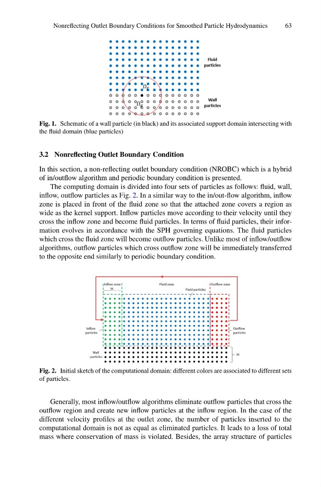
The computing domain is divided into four sets of particles as follows: fluid, wall,
inflow, outflow particles as Fig. 2. In a similar way to the in/out-flow algorithm, inflow
zone is placed in front of the fluid zone so that the attached zone covers a region as
wide as the kernel support. Inflow particles move according to their velocity until they
cross the inflow zone and become fluid particles. In terms of fluid particles, their information evolves in accordance with the SPH governing equations. The fluid particles
which cross the fluid zone will become outflow particles. Unlike most of inflow/outflow
algorithms, outflow particles which cross outflow zone will be immediately transferred
to the opposite end similarly to periodic boundary condition.
Fig. 2. Initial sketch of the computational domain: different colors are associated to different sets
of particles.
Generally, most inflow/outflow algorithms eliminate outflow particles that cross the
outflow region and create new inflow particles at the inflow region. In the case of the
different velocity profiles at the outlet zone, the number of particles inserted to the
computational domain is not as equal as eliminated particles. It leads to a loss of total
mass where conservation of mass is violated. Besides, the array structure of particles
63
Fig. 1. Schematic of a wall particle (in black) and its associated support domain intersecting with
the fluid domain (blue particles)
3.2 Nonreflecting Outlet Boundary Condition
In this section, a non-reflecting outlet boundary condition (NROBC) which is a hybrid
of in/outflow algorithm and periodic boundary condition is presented.
The computing domain is divided into four sets of particles as follows: fluid, wall,
inflow, outflow particles as Fig. 2. In a similar way to the in/out-flow algorithm, inflow
zone is placed in front of the fluid zone so that the attached zone covers a region as
wide as the kernel support. Inflow particles move according to their velocity until they
cross the inflow zone and become fluid particles. In terms of fluid particles, their information evolves in accordance with the SPH governing equations. The fluid particles
which cross the fluid zone will become outflow particles. Unlike most of inflow/outflow
algorithms, outflow particles which cross outflow zone will be immediately transferred
to the opposite end similarly to periodic boundary condition.
Fig. 2. Initial sketch of the computational domain: different colors are associated to different sets
of particles.
Generally, most inflow/outflow algorithms eliminate outflow particles that cross the
outflow region and create new inflow particles at the inflow region. In the case of the
different velocity profiles at the outlet zone, the number of particles inserted to the
computational domain is not as equal as eliminated particles. It leads to a loss of total
mass where conservation of mass is violated. Besides, the array structure of particles