

Preliminary Study on Integrated Simulation
291
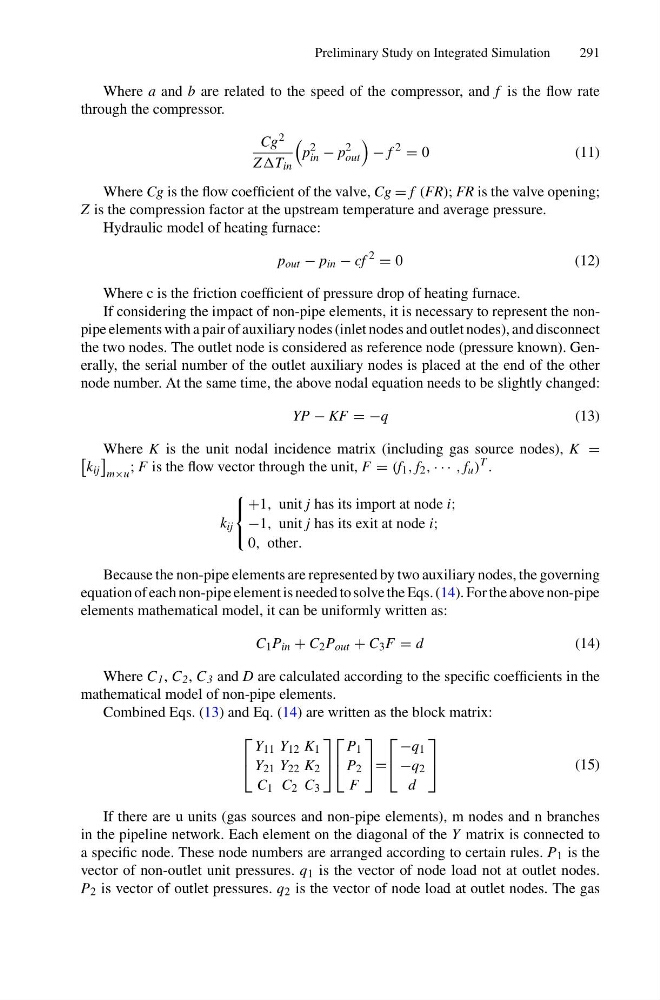
Where a and b are related to the speed of the compressor, and f is the flow rate
through the compressor.
Cg 2
ZT in
p
2
in − p
2
out
− f
2
= 0
(11)
Where Cg is the flow coefficient of the valve, Cg = f (FR); FR is the valve opening;
Z is the compression factor at the upstream temperature and average pressure.
Hydraulic model of heating furnace:
p out − p in − cf
2
= 0
( 1 2 )
Where c is the friction coefficient of pressure drop of heating furnace.
If considering the impact of non-pipe elements, it is necessary to represent the nonpipe elements with a pair of auxiliary nodes (inlet nodes and outlet nodes), and disconnect
the two nodes. The outlet node is considered as reference node (pressure known). Generally, the serial number of the outlet auxiliary nodes is placed at the end of the other
node number. At the same time, the above nodal equation needs to be slightly changed:
YP − KF = −q
(13)
Where K is the unit nodal incidence matrix (including gas source nodes), K =
k ij
m×u
; F is the flow vector through the unit, F = (f 1 , f 2 , · · · , f u )
T .
k ij
⎧
⎨
⎩
+1, unit j has its import at node i;
−1, unit j has its exit at node i;
0, other.
Because the non-pipe elements are represented by two auxiliary nodes, the governing
equation of each non-pipe element is needed to solve the Eqs. (14). For the above non-pipe
elements mathematical model, it can be uniformly written as:
C 1 P in + C 2 P out + C 3 F = d
(14)
Where C 1 , C 2 , C 3 and D are calculated according to the specific coefficients in the
mathematical model of non-pipe elements.
Combined Eqs. (13) and Eq. (14) are written as the block matrix:
⎡
⎣
Y 11 Y 12 K 1
Y 21 Y 22 K 2
C 1 C 2 C 3
⎤
⎦
⎡
⎣
P 1
P 2
F
⎤
⎦ =
⎡
⎣
−q 1
−q 2
d
⎤
⎦
(15)
If there are u units (gas sources and non-pipe elements), m nodes and n branches
in the pipeline network. Each element on the diagonal of the Y matrix is connected to
a specific node. These node numbers are arranged according to certain rules. P 1 is the
vector of non-outlet unit pressures. q 1 is the vector of node load not at outlet nodes.
P 2 is vector of outlet pressures. q 2 is the vector of node load at outlet nodes. The gas
291
Where a and b are related to the speed of the compressor, and f is the flow rate
through the compressor.
Cg 2
ZT in
p
2
in − p
2
out
− f
2
= 0
(11)
Where Cg is the flow coefficient of the valve, Cg = f (FR); FR is the valve opening;
Z is the compression factor at the upstream temperature and average pressure.
Hydraulic model of heating furnace:
p out − p in − cf
2
= 0
( 1 2 )
Where c is the friction coefficient of pressure drop of heating furnace.
If considering the impact of non-pipe elements, it is necessary to represent the nonpipe elements with a pair of auxiliary nodes (inlet nodes and outlet nodes), and disconnect
the two nodes. The outlet node is considered as reference node (pressure known). Generally, the serial number of the outlet auxiliary nodes is placed at the end of the other
node number. At the same time, the above nodal equation needs to be slightly changed:
YP − KF = −q
(13)
Where K is the unit nodal incidence matrix (including gas source nodes), K =
k ij
m×u
; F is the flow vector through the unit, F = (f 1 , f 2 , · · · , f u )
T .
k ij
⎧
⎨
⎩
+1, unit j has its import at node i;
−1, unit j has its exit at node i;
0, other.
Because the non-pipe elements are represented by two auxiliary nodes, the governing
equation of each non-pipe element is needed to solve the Eqs. (14). For the above non-pipe
elements mathematical model, it can be uniformly written as:
C 1 P in + C 2 P out + C 3 F = d
(14)
Where C 1 , C 2 , C 3 and D are calculated according to the specific coefficients in the
mathematical model of non-pipe elements.
Combined Eqs. (13) and Eq. (14) are written as the block matrix:
⎡
⎣
Y 11 Y 12 K 1
Y 21 Y 22 K 2
C 1 C 2 C 3
⎤
⎦
⎡
⎣
P 1
P 2
F
⎤
⎦ =
⎡
⎣
−q 1
−q 2
d
⎤
⎦
(15)
If there are u units (gas sources and non-pipe elements), m nodes and n branches
in the pipeline network. Each element on the diagonal of the Y matrix is connected to
a specific node. These node numbers are arranged according to certain rules. P 1 is the
vector of non-outlet unit pressures. q 1 is the vector of node load not at outlet nodes.
P 2 is vector of outlet pressures. q 2 is the vector of node load at outlet nodes. The gas