

Operating Parameters Optimization of Natural Gas Purification Plant
281
3 Case Study
3.1 Background
This paper simulates the process of a natural gas purification plant in China. This natural
gas purification plant mainly includes gas sweetening unit (GSU), dehydration unit (DU),
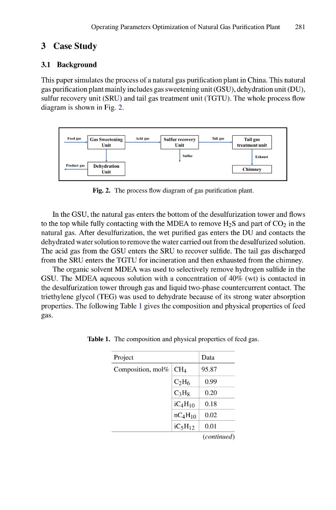
sulfur recovery unit (SRU) and tail gas treatment unit (TGTU). The whole process flow
diagram is shown in Fig. 2.
Fig. 2. The process flow diagram of gas purification plant.
In the GSU, the natural gas enters the bottom of the desulfurization tower and flows
to the top while fully contacting with the MDEA to remove H 2 S and part of CO 2 in the
natural gas. After desulfurization, the wet purified gas enters the DU and contacts the
dehydrated water solution to remove the water carried out from the desulfurized solution.
The acid gas from the GSU enters the SRU to recover sulfide. The tail gas discharged
from the SRU enters the TGTU for incineration and then exhausted from the chimney.
The organic solvent MDEA was used to selectively remove hydrogen sulfide in the
GSU. The MDEA aqueous solution with a concentration of 40% (wt) is contacted in
the desulfurization tower through gas and liquid two-phase countercurrent contact. The
triethylene glycol (TEG) was used to dehydrate because of its strong water absorption
properties. The following Table 1 gives the composition and physical properties of feed
gas.
Table 1. The composition and physical properties of feed gas.
Project
Data
Composition, mol% CH 4
95.87
C 2 H 6
0.99
C 3 H 8
0.20
iC 4 H 10
0.18
nC 4 H 10 0.02
iC 5 H 12
0.01
(continued)
281
3 Case Study
3.1 Background
This paper simulates the process of a natural gas purification plant in China. This natural
gas purification plant mainly includes gas sweetening unit (GSU), dehydration unit (DU),
sulfur recovery unit (SRU) and tail gas treatment unit (TGTU). The whole process flow
diagram is shown in Fig. 2.
Fig. 2. The process flow diagram of gas purification plant.
In the GSU, the natural gas enters the bottom of the desulfurization tower and flows
to the top while fully contacting with the MDEA to remove H 2 S and part of CO 2 in the
natural gas. After desulfurization, the wet purified gas enters the DU and contacts the
dehydrated water solution to remove the water carried out from the desulfurized solution.
The acid gas from the GSU enters the SRU to recover sulfide. The tail gas discharged
from the SRU enters the TGTU for incineration and then exhausted from the chimney.
The organic solvent MDEA was used to selectively remove hydrogen sulfide in the
GSU. The MDEA aqueous solution with a concentration of 40% (wt) is contacted in
the desulfurization tower through gas and liquid two-phase countercurrent contact. The
triethylene glycol (TEG) was used to dehydrate because of its strong water absorption
properties. The following Table 1 gives the composition and physical properties of feed
gas.
Table 1. The composition and physical properties of feed gas.
Project
Data
Composition, mol% CH 4
95.87
C 2 H 6
0.99
C 3 H 8
0.20
iC 4 H 10
0.18
nC 4 H 10 0.02
iC 5 H 12
0.01
(continued)