

266
Y. Xu et al.
4 Case Study
In this section, the performance of the proposed hybrid optimization method is illustrated
by its application to the old gas fields in China. To keep stable production, new blocks
should be connected to the existing gas gathering system and old gathering pipelines
need to be extended and designed.
4.1 Basic Parameters of Gathering System
The data are obtained from a natural gas production enterprise that is responsible for the
operating management for this gas field. There are 37 gathering stations and 8 compressor
stations among them. In the later of the field, new block capacity would be connected to
station 36 and 30. Hence, new pipelines and compressor stations need to be constructed
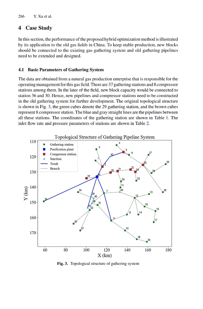
in the old gathering system for further development. The original topological structure
is shown in Fig. 3, the green cubes denote the 29 gathering station, and the brown cubes
represent 8 compressor station. The blue and gray straight lines are the pipelines between
all these stations. The coordinates of the gathering station are shown in Table 1. The
inlet flow rate and pressure parameters of stations are shown in Table 2.
Fig. 3. Topological structure of gathering system
Y. Xu et al.
4 Case Study
In this section, the performance of the proposed hybrid optimization method is illustrated
by its application to the old gas fields in China. To keep stable production, new blocks
should be connected to the existing gas gathering system and old gathering pipelines
need to be extended and designed.
4.1 Basic Parameters of Gathering System
The data are obtained from a natural gas production enterprise that is responsible for the
operating management for this gas field. There are 37 gathering stations and 8 compressor
stations among them. In the later of the field, new block capacity would be connected to
station 36 and 30. Hence, new pipelines and compressor stations need to be constructed
in the old gathering system for further development. The original topological structure
is shown in Fig. 3, the green cubes denote the 29 gathering station, and the brown cubes
represent 8 compressor station. The blue and gray straight lines are the pipelines between
all these stations. The coordinates of the gathering station are shown in Table 1. The
inlet flow rate and pressure parameters of stations are shown in Table 2.
Fig. 3. Topological structure of gathering system