

152
R. Zhang et al.
Area-I
Area-II
Area-III
3500m
2500m
4000m
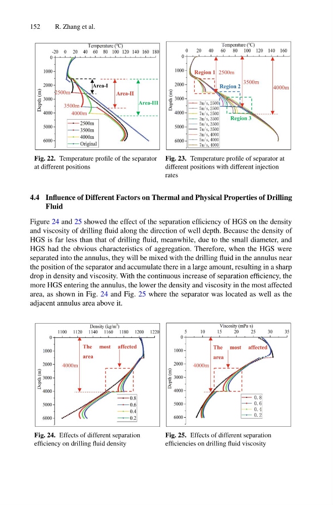
Fig. 22. Temperature profile of the separator
at different positions
2500m
3500m
4000m
Region 1
Region 2
Region 3
Fig. 23. Temperature profile of separator at
different positions with different injection
rates
4.4 Influence of Different Factors on Thermal and Physical Properties of Drilling
Fluid
Figure 24 and 25 showed the effect of the separation efficiency of HGS on the density
and viscosity of drilling fluid along the direction of well depth. Because the density of
HGS is far less than that of drilling fluid, meanwhile, due to the small diameter, and
HGS had the obvious characteristics of aggregation. Therefore, when the HGS were
separated into the annulus, they will be mixed with the drilling fluid in the annulus near
the position of the separator and accumulate there in a large amount, resulting in a sharp
drop in density and viscosity. With the continuous increase of separation efficiency, the
more HGS entering the annulus, the lower the density and viscosity in the most affected
area, as shown in Fig. 24 and Fig. 25 where the separator was located as well as the
adjacent annulus area above it.
4000m
The most affected
area
Fig. 24. Effects of different separation
efficiency on drilling fluid density
4000m
The most affected
area
Fig. 25. Effects of different separation
efficiencies on drilling fluid viscosity
R. Zhang et al.
Area-I
Area-II
Area-III
3500m
2500m
4000m
Fig. 22. Temperature profile of the separator
at different positions
2500m
3500m
4000m
Region 1
Region 2
Region 3
Fig. 23. Temperature profile of separator at
different positions with different injection
rates
4.4 Influence of Different Factors on Thermal and Physical Properties of Drilling
Fluid
Figure 24 and 25 showed the effect of the separation efficiency of HGS on the density
and viscosity of drilling fluid along the direction of well depth. Because the density of
HGS is far less than that of drilling fluid, meanwhile, due to the small diameter, and
HGS had the obvious characteristics of aggregation. Therefore, when the HGS were
separated into the annulus, they will be mixed with the drilling fluid in the annulus near
the position of the separator and accumulate there in a large amount, resulting in a sharp
drop in density and viscosity. With the continuous increase of separation efficiency, the
more HGS entering the annulus, the lower the density and viscosity in the most affected
area, as shown in Fig. 24 and Fig. 25 where the separator was located as well as the
adjacent annulus area above it.
4000m
The most affected
area
Fig. 24. Effects of different separation
efficiency on drilling fluid density
4000m
The most affected
area
Fig. 25. Effects of different separation
efficiencies on drilling fluid viscosity