

72
C. Neugebauer et al.
n i =
J
j=1
n i, j .
(2)
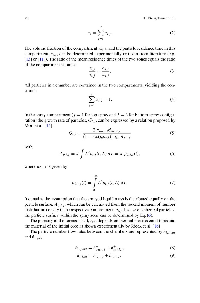
The volume fraction of the compartment, ω i, j , and the particle residence time in this
compartment, τ i, j , can be determined experimentally or taken from literature (e.g.
[13] or [11]). The ratio of the mean residence times of the two zones equals the ratio
of the compartment volumes:
τ i, j
τ i, ¯
j
=
ω i, j
ω i, ¯
j
.
(3)
All particles in a chamber are contained in the two compartments, yielding the constraint:
2
j=1
ω i, j = 1.
(4)
In the spray compartment ( j = 1 for top-spray and j = 2 for bottom-spray configuration) the growth rate of particles, G i, j , can be expressed by a relation proposed by
Mörl et al. [15]:
G i, j =
2 y sus,s M sus,i, j
1 − sh (η dr y,i )
s A p,i, j
(5)
with
A p,i, j = π
L
2 n i, j (t, L) d L = π μ 2,i, j (t),
(6)
where μ 2,i, j is given by
μ 2,i, j (t) =
∞
0
L
2 n i, j (t, L) d L.
(7)
It contains the assumption that the sprayed liquid mass is distributed equally on the
particle surface, A p,i, j , which can be calculated from the second moment of number
distribution density in the respective compartment, n i, j . In case of spherical particles,
the particle surface within the spray zone can be determined by Eq. (6).
The porosity of the formed shell, sh , depends on thermal process conditions and
the material of the initial core as shown experimentally by Rieck et al. [16].
The particle number flow rates between the chambers are represented by ˙
n i, j,out
and ˙
n i, j,in :
˙
n i, j,out = ˙
n
−
out,i, j + ˙
n
+
out,i, j ,
(8)
˙
n i, j,in = ˙
n
−
in,i, j + ˙
n
+
in,i, j ,
(9)
C. Neugebauer et al.
n i =
J
j=1
n i, j .
(2)
The volume fraction of the compartment, ω i, j , and the particle residence time in this
compartment, τ i, j , can be determined experimentally or taken from literature (e.g.
[13] or [11]). The ratio of the mean residence times of the two zones equals the ratio
of the compartment volumes:
τ i, j
τ i, ¯
j
=
ω i, j
ω i, ¯
j
.
(3)
All particles in a chamber are contained in the two compartments, yielding the constraint:
2
j=1
ω i, j = 1.
(4)
In the spray compartment ( j = 1 for top-spray and j = 2 for bottom-spray configuration) the growth rate of particles, G i, j , can be expressed by a relation proposed by
Mörl et al. [15]:
G i, j =
2 y sus,s M sus,i, j
1 − sh (η dr y,i )
s A p,i, j
(5)
with
A p,i, j = π
L
2 n i, j (t, L) d L = π μ 2,i, j (t),
(6)
where μ 2,i, j is given by
μ 2,i, j (t) =
∞
0
L
2 n i, j (t, L) d L.
(7)
It contains the assumption that the sprayed liquid mass is distributed equally on the
particle surface, A p,i, j , which can be calculated from the second moment of number
distribution density in the respective compartment, n i, j . In case of spherical particles,
the particle surface within the spray zone can be determined by Eq. (6).
The porosity of the formed shell, sh , depends on thermal process conditions and
the material of the initial core as shown experimentally by Rieck et al. [16].
The particle number flow rates between the chambers are represented by ˙
n i, j,out
and ˙
n i, j,in :
˙
n i, j,out = ˙
n
−
out,i, j + ˙
n
+
out,i, j ,
(8)
˙
n i, j,in = ˙
n
−
in,i, j + ˙
n
+
in,i, j ,
(9)