

52
L. Lindmüller et al.
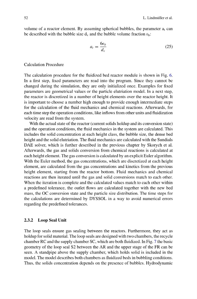
volume of a reactor element. By assuming spherical bubbles, the parameter a t can
be described with the bubble size d v and the bubble volume fraction ε b :
a t =
6 b
d v
(25)
Calculation Procedure
The calculation procedure for the fluidized bed reactor module is shown in Fig. 6.
In a first step, fixed parameters are read into the program. Since they cannot be
changed during the simulation, they are only initialized once. Examples for fixed
parameters are geometrical values or the particle elutriation model. In a next step,
the reactor is discretized in a number of height elements over the reactor height. It
is important to choose a number high enough to provide enough intermediate steps
for the calculation of the fluid mechanics and chemical reactions. Afterwards, for
each time step the operation conditions, like inflows from other units and fluidization
velocity are read from the system.
With the actual state of the reactor (current solids holdup and its conversion state)
and the operation conditions, the fluid mechanics in the system are calculated. This
includes the solid concentration at each height class, the bubble size, the dense bed
height and the solid elutriation. The fluid mechanics are calculated with the Sundials
DAE solver, which is further described in the previous chapter by Skorych et al.
Afterwards, the gas and solids conversion from chemical reactions is calculated at
each height element. The gas conversion is calculated by an explicit Euler algorithm.
With the Euler method, the gas concentrations, which are discretized at each height
element, are calculated from the gas concentrations and kinetics from the previous
height element, starting from the reactor bottom. Fluid mechanics and chemical
reactions are then iterated until the gas and solid conversions match to each other.
When the iteration is complete and the calculated values match to each other within
a predefined tolerance, the outlet flows are calculated together with the new bed
mass, the OC conversion state and the particle size distribution. The time steps for
the calculations are determined by DYSSOL in a way to avoid numerical errors
regarding the predefined tolerances.
2.3.2 Loop Seal Unit
The loop seals ensure gas sealing between the reactors. Furthermore, they act as
holdup for solid material. The loop seals are designed with two chambers, the recycle
chamber RC and the supply chamber SC, which are both fluidized. In Fig. 7 the basic
geometry of the loop seal S2 between the AR and the upper stage of the FR can be
seen. A standpipe above the supply chamber, which holds solid is included in the
model. The model describes both chambers as fluidized beds in bubbling conditions.
Thus, the solids concentration depends on the presence of bubbles. Hydrodynamic
L. Lindmüller et al.
volume of a reactor element. By assuming spherical bubbles, the parameter a t can
be described with the bubble size d v and the bubble volume fraction ε b :
a t =
6 b
d v
(25)
Calculation Procedure
The calculation procedure for the fluidized bed reactor module is shown in Fig. 6.
In a first step, fixed parameters are read into the program. Since they cannot be
changed during the simulation, they are only initialized once. Examples for fixed
parameters are geometrical values or the particle elutriation model. In a next step,
the reactor is discretized in a number of height elements over the reactor height. It
is important to choose a number high enough to provide enough intermediate steps
for the calculation of the fluid mechanics and chemical reactions. Afterwards, for
each time step the operation conditions, like inflows from other units and fluidization
velocity are read from the system.
With the actual state of the reactor (current solids holdup and its conversion state)
and the operation conditions, the fluid mechanics in the system are calculated. This
includes the solid concentration at each height class, the bubble size, the dense bed
height and the solid elutriation. The fluid mechanics are calculated with the Sundials
DAE solver, which is further described in the previous chapter by Skorych et al.
Afterwards, the gas and solids conversion from chemical reactions is calculated at
each height element. The gas conversion is calculated by an explicit Euler algorithm.
With the Euler method, the gas concentrations, which are discretized at each height
element, are calculated from the gas concentrations and kinetics from the previous
height element, starting from the reactor bottom. Fluid mechanics and chemical
reactions are then iterated until the gas and solid conversions match to each other.
When the iteration is complete and the calculated values match to each other within
a predefined tolerance, the outlet flows are calculated together with the new bed
mass, the OC conversion state and the particle size distribution. The time steps for
the calculations are determined by DYSSOL in a way to avoid numerical errors
regarding the predefined tolerances.
2.3.2 Loop Seal Unit
The loop seals ensure gas sealing between the reactors. Furthermore, they act as
holdup for solid material. The loop seals are designed with two chambers, the recycle
chamber RC and the supply chamber SC, which are both fluidized. In Fig. 7 the basic
geometry of the loop seal S2 between the AR and the upper stage of the FR can be
seen. A standpipe above the supply chamber, which holds solid is included in the
model. The model describes both chambers as fluidized beds in bubbling conditions.
Thus, the solids concentration depends on the presence of bubbles. Hydrodynamic