

15 Compartmental Population Balances by Means of Monte Carlo Methods
537
3.2.1 Transport of Weighted MC Particles
In the following, the transport of MC particles from one compartment to other compartments will be described. It consists of two steps: (1) the particle outflow and
(2) the particle inflow. This is being realized by the computational implementation
of ‘streams’ which are able to store a population of MC particles, as large as the
population stored for each compartment.
In the first outflow step, particles are inserted into the streams. This can be easily
done by copying all particles from the hold-up into the stream and adjusting the
statistical weights accordingly, in the stream and in the hold-up. If, for example, the
particles from compartment 1 stream into compartment 2 with the size v dependent
relative rate f 1→2 (v), then one can describe for each particle i the change of its
statistical weight W i for a small interval of time as:
W i (t + = W i (t) − · f 1→2 (v i ) · W i (t)
(15)
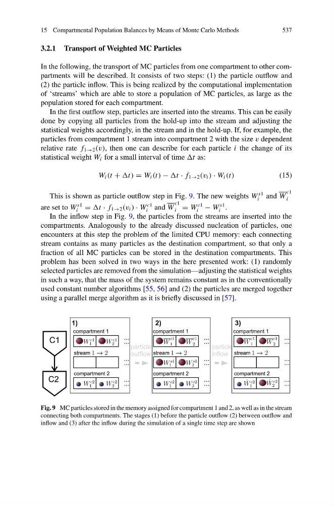
This is shown as particle outflow step in Fig. 9. The new weights W
s1
i and W
c1
i
are set to W
s1
i = · f 1→2 (v i ) · W
c1
i and W
c1
i = W
c1
i − W
s1
i .
In the inflow step in Fig. 9, the particles from the streams are inserted into the
compartments. Analogously to the already discussed nucleation of particles, one
encounters at this step the problem of the limited CPU memory: each connecting
stream contains as many particles as the destination compartment, so that only a
fraction of all MC particles can be stored in the destination compartments. This
problem has been solved in two ways in the here presented work: (1) randomly
selected particles are removed from the simulation—adjusting the statistical weights
in such a way, that the mass of the system remains constant as in the conventionally
used constant number algorithms [55, 56] and (2) the particles are merged together
using a parallel merge algorithm as it is briefly discussed in [57].
Fig. 9 MC particles stored in the memory assigned for compartment 1 and 2, as well as in the stream
connecting both compartments. The stages (1) before the particle outflow (2) between outflow and
inflow and (3) after the inflow during the simulation of a single time step are shown
537
3.2.1 Transport of Weighted MC Particles
In the following, the transport of MC particles from one compartment to other compartments will be described. It consists of two steps: (1) the particle outflow and
(2) the particle inflow. This is being realized by the computational implementation
of ‘streams’ which are able to store a population of MC particles, as large as the
population stored for each compartment.
In the first outflow step, particles are inserted into the streams. This can be easily
done by copying all particles from the hold-up into the stream and adjusting the
statistical weights accordingly, in the stream and in the hold-up. If, for example, the
particles from compartment 1 stream into compartment 2 with the size v dependent
relative rate f 1→2 (v), then one can describe for each particle i the change of its
statistical weight W i for a small interval of time as:
W i (t + = W i (t) − · f 1→2 (v i ) · W i (t)
(15)
This is shown as particle outflow step in Fig. 9. The new weights W
s1
i and W
c1
i
are set to W
s1
i = · f 1→2 (v i ) · W
c1
i and W
c1
i = W
c1
i − W
s1
i .
In the inflow step in Fig. 9, the particles from the streams are inserted into the
compartments. Analogously to the already discussed nucleation of particles, one
encounters at this step the problem of the limited CPU memory: each connecting
stream contains as many particles as the destination compartment, so that only a
fraction of all MC particles can be stored in the destination compartments. This
problem has been solved in two ways in the here presented work: (1) randomly
selected particles are removed from the simulation—adjusting the statistical weights
in such a way, that the mass of the system remains constant as in the conventionally
used constant number algorithms [55, 56] and (2) the particles are merged together
using a parallel merge algorithm as it is briefly discussed in [57].
Fig. 9 MC particles stored in the memory assigned for compartment 1 and 2, as well as in the stream
connecting both compartments. The stages (1) before the particle outflow (2) between outflow and
inflow and (3) after the inflow during the simulation of a single time step are shown