

2 Dynamic Modelling of Reactive Fluidized Bed Systems Using …
43
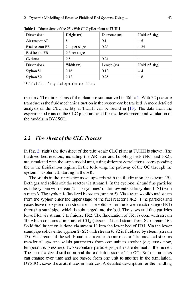
Table 1 Dimensions of the 25 kWth CLC pilot-plant at TUHH
Dimensions
Height (m)
Diameter (m)
Holdup a (kg)
Air reactor AR
8
0.1
~ 5
Fuel reactor FR
2 m per stage
0.25
~ 24
Bed height FR
0.6 per stage
Cyclone
0.34
0.21
–
Dimensions
Width (m)
Length (m)
Holdup a (kg)
Siphon S1
0.16
0.13
~ 4
Siphon S2
0.13
0.25
~ 8
a Solids holdup for typical operation conditions
reactors. The dimensions of the plant are summarized in Table 1. With 32 pressure
transducers the fluid mechanic situation in the system can be tracked. A more detailed
analysis of the CLC facility at TUHH can be found in [13]. The data from the
experimental runs on the CLC plant are used for the development and validation of
the models in DYSSOL.
2.2 Flowsheet of the CLC Process
In Fig. 2 (right) the flowsheet of the pilot-scale CLC plant at TUHH is shown. The
fluidized bed reactors, including the AR riser and bubbling beds (FR1 and FR2),
are simulated with the same model unit, using different correlations, corresponding
the to the fluidization regime. In the following, the pathway of the OC through the
system is explained, starting in the AR.
The solids in the air reactor move upwards with the fluidization air (stream 15).
Both gas and solids exit the reactor via stream 1. In the cyclone, air and fine particles
exit the system with stream 2. The cyclones’ underflow enters the syphon 1 (S1) with
stream 3. The syphon is fluidized by steam (stream 5). Via stream 4 solids and steam
from the syphon enter the upper stage of the fuel reactor (FR2). Fine particles and
gases leave the system via stream 6. The solids enter the lower reactor stage (FR1)
through a standpipe, which is submerged into the bed. The gases and fine particles
leave FR1 via stream 7 to fluidize FR2. The fluidization of FR1 is done with stream
10, which contains a mixture of CO 2 (stream 12) and steam from S2 (stream 16).
Solid fuel injection is done via stream 11 into the lower bed of FR1. Via the lower
standpipe solids enter syphon 2 (S2) with stream 9. S2 is fluidized by steam (stream
13). Via stream 14 the solids and steam enter the air reactor. The modeled streams
transfer all gas and solids parameters from one unit to another (e.g. mass flow,
temperature, pressure). Two secondary particle properties are defined in the model:
The particle size distribution and the oxidation state of the OC. Both parameters
can change over time and are passed from one unit to another in the simulation.
DYSSOL saves these attributes in matrices. A detailed description for the handling
43
Table 1 Dimensions of the 25 kWth CLC pilot-plant at TUHH
Dimensions
Height (m)
Diameter (m)
Holdup a (kg)
Air reactor AR
8
0.1
~ 5
Fuel reactor FR
2 m per stage
0.25
~ 24
Bed height FR
0.6 per stage
Cyclone
0.34
0.21
–
Dimensions
Width (m)
Length (m)
Holdup a (kg)
Siphon S1
0.16
0.13
~ 4
Siphon S2
0.13
0.25
~ 8
a Solids holdup for typical operation conditions
reactors. The dimensions of the plant are summarized in Table 1. With 32 pressure
transducers the fluid mechanic situation in the system can be tracked. A more detailed
analysis of the CLC facility at TUHH can be found in [13]. The data from the
experimental runs on the CLC plant are used for the development and validation of
the models in DYSSOL.
2.2 Flowsheet of the CLC Process
In Fig. 2 (right) the flowsheet of the pilot-scale CLC plant at TUHH is shown. The
fluidized bed reactors, including the AR riser and bubbling beds (FR1 and FR2),
are simulated with the same model unit, using different correlations, corresponding
the to the fluidization regime. In the following, the pathway of the OC through the
system is explained, starting in the AR.
The solids in the air reactor move upwards with the fluidization air (stream 15).
Both gas and solids exit the reactor via stream 1. In the cyclone, air and fine particles
exit the system with stream 2. The cyclones’ underflow enters the syphon 1 (S1) with
stream 3. The syphon is fluidized by steam (stream 5). Via stream 4 solids and steam
from the syphon enter the upper stage of the fuel reactor (FR2). Fine particles and
gases leave the system via stream 6. The solids enter the lower reactor stage (FR1)
through a standpipe, which is submerged into the bed. The gases and fine particles
leave FR1 via stream 7 to fluidize FR2. The fluidization of FR1 is done with stream
10, which contains a mixture of CO 2 (stream 12) and steam from S2 (stream 16).
Solid fuel injection is done via stream 11 into the lower bed of FR1. Via the lower
standpipe solids enter syphon 2 (S2) with stream 9. S2 is fluidized by steam (stream
13). Via stream 14 the solids and steam enter the air reactor. The modeled streams
transfer all gas and solids parameters from one unit to another (e.g. mass flow,
temperature, pressure). Two secondary particle properties are defined in the model:
The particle size distribution and the oxidation state of the OC. Both parameters
can change over time and are passed from one unit to another in the simulation.
DYSSOL saves these attributes in matrices. A detailed description for the handling