

42
L. Lindmüller et al.
2 Materials and Methods
2.1 Experimental Facility
A 25 kWth experimental CLC pilot plant is operated at Hamburg University of
Technology. The plant is run with an oxygen carrier consisting of 9 wt% CuO on
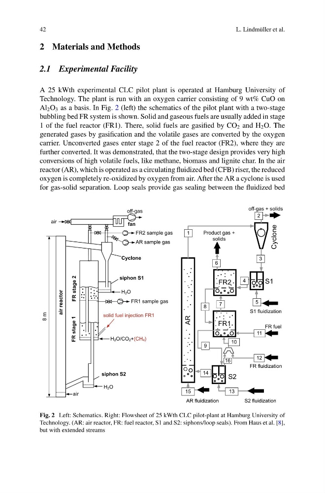
Al 2 O 3 as a basis. In Fig. 2 (left) the schematics of the pilot plant with a two-stage
bubbling bed FR system is shown. Solid and gaseous fuels are usually added in stage
1 of the fuel reactor (FR1). There, solid fuels are gasified by CO 2 and H 2 O. The
generated gases by gasification and the volatile gases are converted by the oxygen
carrier. Unconverted gases enter stage 2 of the fuel reactor (FR2), where they are
further converted. It was demonstrated, that the two-stage design provides very high
conversions of high volatile fuels, like methane, biomass and lignite char. In the air
reactor (AR), which is operated as a circulating fluidized bed (CFB) riser, the reduced
oxygen is completely re-oxidized by oxygen from air. After the AR a cyclone is used
for gas-solid separation. Loop seals provide gas sealing between the fluidized bed
FR stage 1
Cyclone
air reactor
H2O
H2O/CO2+(CH4)
H2O
air
air
fan
solid fuel injection FR1
off-gas
8 m
FR stage 2
siphon S1
siphon S2
FR1 sample gas
FR2 sample gas
AR sample gas
FR1
FR2
1
2
AR
S1
S2
Cyclone
14
9
8
Product gas +
solids
7
FR fluidization
S2 fluidization
5
AR fluidization
4
6
3
off-gas + solids
S1 fluidization
13
15
10
FR fuel
12
11
16
Fig. 2 Left: Schematics. Right: Flowsheet of 25 kWth CLC pilot-plant at Hamburg University of
Technology. (AR: air reactor, FR: fuel reactor, S1 and S2: siphons/loop seals). From Haus et al. [8],
but with extended streams
L. Lindmüller et al.
2 Materials and Methods
2.1 Experimental Facility
A 25 kWth experimental CLC pilot plant is operated at Hamburg University of
Technology. The plant is run with an oxygen carrier consisting of 9 wt% CuO on
Al 2 O 3 as a basis. In Fig. 2 (left) the schematics of the pilot plant with a two-stage
bubbling bed FR system is shown. Solid and gaseous fuels are usually added in stage
1 of the fuel reactor (FR1). There, solid fuels are gasified by CO 2 and H 2 O. The
generated gases by gasification and the volatile gases are converted by the oxygen
carrier. Unconverted gases enter stage 2 of the fuel reactor (FR2), where they are
further converted. It was demonstrated, that the two-stage design provides very high
conversions of high volatile fuels, like methane, biomass and lignite char. In the air
reactor (AR), which is operated as a circulating fluidized bed (CFB) riser, the reduced
oxygen is completely re-oxidized by oxygen from air. After the AR a cyclone is used
for gas-solid separation. Loop seals provide gas sealing between the fluidized bed
FR stage 1
Cyclone
air reactor
H2O
H2O/CO2+(CH4)
H2O
air
air
fan
solid fuel injection FR1
off-gas
8 m
FR stage 2
siphon S1
siphon S2
FR1 sample gas
FR2 sample gas
AR sample gas
FR1
FR2
1
2
AR
S1
S2
Cyclone
14
9
8
Product gas +
solids
7
FR fluidization
S2 fluidization
5
AR fluidization
4
6
3
off-gas + solids
S1 fluidization
13
15
10
FR fuel
12
11
16
Fig. 2 Left: Schematics. Right: Flowsheet of 25 kWth CLC pilot-plant at Hamburg University of
Technology. (AR: air reactor, FR: fuel reactor, S1 and S2: siphons/loop seals). From Haus et al. [8],
but with extended streams