

468
S. Schiele et al.
its circular path. Inside the outer zone B Braun considers a cylindrical inner zone C
where the fluid moves upwards towards the outlet where the overflow is withdrawn.
The model assumes material transport between the zones that is dependent on
particle sizes. Larger particles are drawn to the outer wall by centrifugal force and
are added to the underflow if they are large enough to touch the outer wall of the
zones A and B. Particles that reach the top of zone C are added to the overflow. The
reflux parameter R f =
˙
V overflow
˙
V feed
is used to define which proportion of a feed suspension
is leaving the cyclone through the overflow.
5.3 Flowsheet and Simulation Results
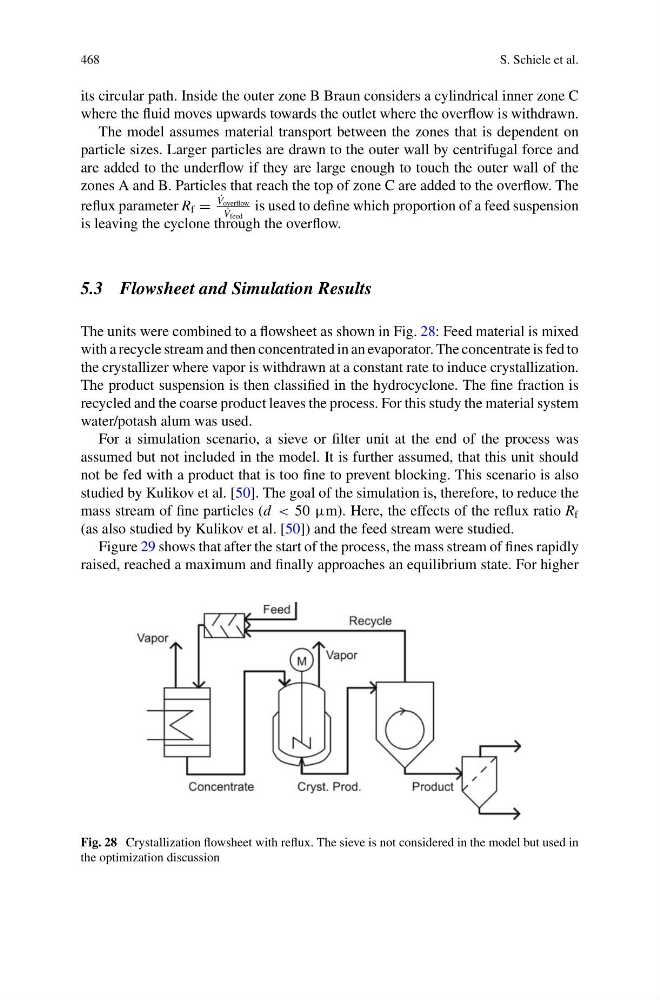
The units were combined to a flowsheet as shown in Fig. 28: Feed material is mixed
with a recycle stream and then concentrated in an evaporator. The concentrate is fed to
the crystallizer where vapor is withdrawn at a constant rate to induce crystallization.
The product suspension is then classified in the hydrocyclone. The fine fraction is
recycled and the coarse product leaves the process. For this study the material system
water/potash alum was used.
For a simulation scenario, a sieve or filter unit at the end of the process was
assumed but not included in the model. It is further assumed, that this unit should
not be fed with a product that is too fine to prevent blocking. This scenario is also
studied by Kulikov et al. [50]. The goal of the simulation is, therefore, to reduce the
mass stream of fine particles (d < 50 μm). Here, the effects of the reflux ratio R f
(as also studied by Kulikov et al. [50]) and the feed stream were studied.
Figure 29 shows that after the start of the process, the mass stream of fines rapidly
raised, reached a maximum and finally approaches an equilibrium state. For higher
Fig. 28 Crystallization flowsheet with reflux. The sieve is not considered in the model but used in
the optimization discussion
S. Schiele et al.
its circular path. Inside the outer zone B Braun considers a cylindrical inner zone C
where the fluid moves upwards towards the outlet where the overflow is withdrawn.
The model assumes material transport between the zones that is dependent on
particle sizes. Larger particles are drawn to the outer wall by centrifugal force and
are added to the underflow if they are large enough to touch the outer wall of the
zones A and B. Particles that reach the top of zone C are added to the overflow. The
reflux parameter R f =
˙
V overflow
˙
V feed
is used to define which proportion of a feed suspension
is leaving the cyclone through the overflow.
5.3 Flowsheet and Simulation Results
The units were combined to a flowsheet as shown in Fig. 28: Feed material is mixed
with a recycle stream and then concentrated in an evaporator. The concentrate is fed to
the crystallizer where vapor is withdrawn at a constant rate to induce crystallization.
The product suspension is then classified in the hydrocyclone. The fine fraction is
recycled and the coarse product leaves the process. For this study the material system
water/potash alum was used.
For a simulation scenario, a sieve or filter unit at the end of the process was
assumed but not included in the model. It is further assumed, that this unit should
not be fed with a product that is too fine to prevent blocking. This scenario is also
studied by Kulikov et al. [50]. The goal of the simulation is, therefore, to reduce the
mass stream of fine particles (d < 50 μm). Here, the effects of the reflux ratio R f
(as also studied by Kulikov et al. [50]) and the feed stream were studied.
Figure 29 shows that after the start of the process, the mass stream of fines rapidly
raised, reached a maximum and finally approaches an equilibrium state. For higher
Fig. 28 Crystallization flowsheet with reflux. The sieve is not considered in the model but used in
the optimization discussion