

40
L. Lindmüller et al.
Indices
0
Initial
b
Bubble
d
Dense suspension phases
f
Freeboard
i
Particle size class
j
Solid component
l
Gas component
1 Introduction
Chemical Looping Combustion (CLC) is a promising CO 2 capturing technology,
which might find future use for electricity generation or in industrial processes where
industrial firing systems are needed. Instead of direct air combustion, in CLC an oxygen carrying material (OC), usually a metal oxide, is circulated between a fuel reactor
(FR) and an air reactor (AR). The OC is reduced by the fuel in the FR and re-oxidized
in the AR by air. By avoiding contact with the fuel and air, a combustion in absence
of nitrogen is realized and a flue gas stream of almost pure CO 2 and H 2 O is generated
in the FR. The pure CO 2 can then be used for underground storage in suitable geological formations, such as empty natural gas caverns. This process is called Carbon
Capture and Storage (CCS). The basic process schematics of the investigated CLC
configuration, called in-situ Gasification Chemical Looping Combustion (iG-CLC)
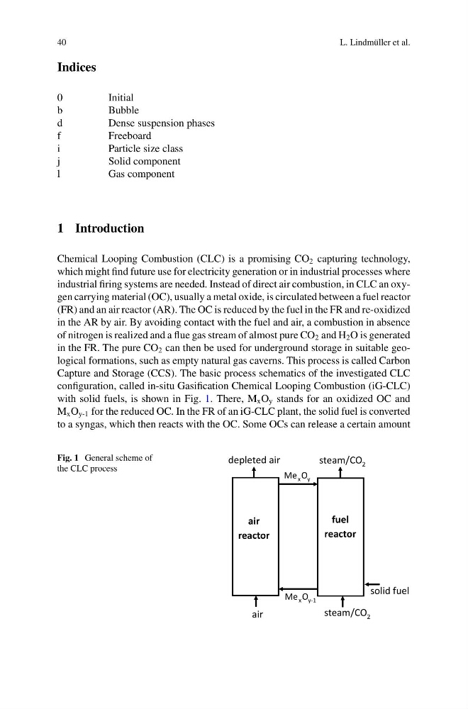
with solid fuels, is shown in Fig. 1. There, M x O y stands for an oxidized OC and
M x O y-1 for the reduced OC. In the FR of an iG-CLC plant, the solid fuel is converted
to a syngas, which then reacts with the OC. Some OCs can release a certain amount
Fig. 1 General scheme of
the CLC process
depleted air
steam/CO 2
steam/CO 2
air
fuel
reactor
air
reactor
Me x O y
Me x O y-1
solid fuel
L. Lindmüller et al.
Indices
0
Initial
b
Bubble
d
Dense suspension phases
f
Freeboard
i
Particle size class
j
Solid component
l
Gas component
1 Introduction
Chemical Looping Combustion (CLC) is a promising CO 2 capturing technology,
which might find future use for electricity generation or in industrial processes where
industrial firing systems are needed. Instead of direct air combustion, in CLC an oxygen carrying material (OC), usually a metal oxide, is circulated between a fuel reactor
(FR) and an air reactor (AR). The OC is reduced by the fuel in the FR and re-oxidized
in the AR by air. By avoiding contact with the fuel and air, a combustion in absence
of nitrogen is realized and a flue gas stream of almost pure CO 2 and H 2 O is generated
in the FR. The pure CO 2 can then be used for underground storage in suitable geological formations, such as empty natural gas caverns. This process is called Carbon
Capture and Storage (CCS). The basic process schematics of the investigated CLC
configuration, called in-situ Gasification Chemical Looping Combustion (iG-CLC)
with solid fuels, is shown in Fig. 1. There, M x O y stands for an oxidized OC and
M x O y-1 for the reduced OC. In the FR of an iG-CLC plant, the solid fuel is converted
to a syngas, which then reacts with the OC. Some OCs can release a certain amount
Fig. 1 General scheme of
the CLC process
depleted air
steam/CO 2
steam/CO 2
air
fuel
reactor
air
reactor
Me x O y
Me x O y-1
solid fuel