

9 Impact Comminution in Jet Mills
343
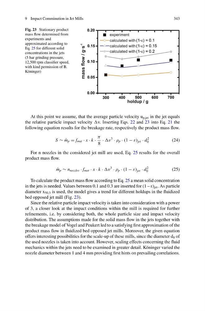
Fig. 23 Stationary product
mass flow determined from
experiments and
approximated according to
Eq. 25 for different solid
concentrations in the jets
(5 bar grinding pressure,
12,500 rpm classifier speed,
with kind permission of B.
Köninger)
At this point we assume, that the average particle velocity u p,jet in the jet equals
the relative particle impact velocity v. Inserting Eqs. 22 and 23 into Eq. 21 the
following equation results for the breakage rate, respectively the product mass flow.
S ∼ ˙
m p = f mat · x · k ·
π
8
· v
3
· ρ p · (1 − ε) jet · d
2
0
(24)
For n nozzles in the considered jet mill are used, Eq. 25 results for the overall
product mass flow.
˙
m p ∼ n nozzles · f mat · x · k · v
3
· ρ p · (1 − ε) jet · d
2
0
(25)
To calculate the product mass flow according to Eq. 25 a mean solid concentration
in the jets is needed. Values between 0.1 and 0.3 are inserted for (1 – ε) jet . As particle
diameter x 50,3 is used, the model gives a trend for different holdups in the fluidized
bed opposed jet mill (Fig. 23).
Since the relative particle impact velocity is taken into consideration with a power
of 3, a closer look at the impact conditions within the mill is required for further
refinements, i.e. by considering both, the whole particle size and impact velocity
distribution. The assumptions made for the solid mass flow in the jets together with
the breakage model of Vogel and Peukert led to a satisfying first approximation of the
product mass flow in fluidized bed opposed jet mills. Moreover, the given equation
offers interesting possibilities for the scale-up of these mills, since the diameter d 0 of
the used nozzles is taken into account. However, scaling effects concerning the fluid
mechanics within the jets need to be examined in greater detail. Köninger varied the
nozzle diameter between 1 and 4 mm providing first hints on prevailing correlations.
343
Fig. 23 Stationary product
mass flow determined from
experiments and
approximated according to
Eq. 25 for different solid
concentrations in the jets
(5 bar grinding pressure,
12,500 rpm classifier speed,
with kind permission of B.
Köninger)
At this point we assume, that the average particle velocity u p,jet in the jet equals
the relative particle impact velocity v. Inserting Eqs. 22 and 23 into Eq. 21 the
following equation results for the breakage rate, respectively the product mass flow.
S ∼ ˙
m p = f mat · x · k ·
π
8
· v
3
· ρ p · (1 − ε) jet · d
2
0
(24)
For n nozzles in the considered jet mill are used, Eq. 25 results for the overall
product mass flow.
˙
m p ∼ n nozzles · f mat · x · k · v
3
· ρ p · (1 − ε) jet · d
2
0
(25)
To calculate the product mass flow according to Eq. 25 a mean solid concentration
in the jets is needed. Values between 0.1 and 0.3 are inserted for (1 – ε) jet . As particle
diameter x 50,3 is used, the model gives a trend for different holdups in the fluidized
bed opposed jet mill (Fig. 23).
Since the relative particle impact velocity is taken into consideration with a power
of 3, a closer look at the impact conditions within the mill is required for further
refinements, i.e. by considering both, the whole particle size and impact velocity
distribution. The assumptions made for the solid mass flow in the jets together with
the breakage model of Vogel and Peukert led to a satisfying first approximation of the
product mass flow in fluidized bed opposed jet mills. Moreover, the given equation
offers interesting possibilities for the scale-up of these mills, since the diameter d 0 of
the used nozzles is taken into account. However, scaling effects concerning the fluid
mechanics within the jets need to be examined in greater detail. Köninger varied the
nozzle diameter between 1 and 4 mm providing first hints on prevailing correlations.