

338
A. Strobel et al.
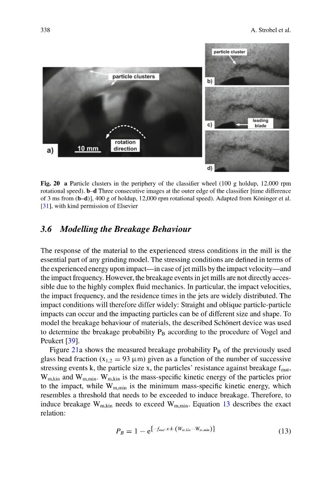
Fig. 20 a Particle clusters in the periphery of the classifier wheel (100 g holdup, 12,000 rpm
rotational speed). b–d Three consecutive images at the outer edge of the classifier [time difference
of 3 ms from (b–d)], 400 g of holdup, 12,000 rpm rotational speed). Adapted from Köninger et al.
[31], with kind permission of Elsevier
3.6 Modelling the Breakage Behaviour
The response of the material to the experienced stress conditions in the mill is the
essential part of any grinding model. The stressing conditions are defined in terms of
the experienced energy upon impact—in case of jet mills by the impact velocity—and
the impact frequency. However, the breakage events in jet mills are not directly accessible due to the highly complex fluid mechanics. In particular, the impact velocities,
the impact frequency, and the residence times in the jets are widely distributed. The
impact conditions will therefore differ widely: Straight and oblique particle-particle
impacts can occur and the impacting particles can be of different size and shape. To
model the breakage behaviour of materials, the described Schönert device was used
to determine the breakage probability P B according to the procedure of Vogel and
Peukert [39].
Figure 21a shows the measured breakage probability P B of the previously used
glass bead fraction (x 1,2 = 93 μm) given as a function of the number of successive
stressing events k, the particle size x, the particles’ resistance against breakage f mat ,
W m,kin and W m,min . W m,kin is the mass-specific kinetic energy of the particles prior
to the impact, while W m,min is the minimum mass-specific kinetic energy, which
resembles a threshold that needs to be exceeded to induce breakage. Therefore, to
induce breakage W m,kin needs to exceed W m,min . Equation 13 describes the exact
relation:
P B = 1 − e {−fmat·x·k·(Wm,kin−Wm,min)}
(13)
A. Strobel et al.
Fig. 20 a Particle clusters in the periphery of the classifier wheel (100 g holdup, 12,000 rpm
rotational speed). b–d Three consecutive images at the outer edge of the classifier [time difference
of 3 ms from (b–d)], 400 g of holdup, 12,000 rpm rotational speed). Adapted from Köninger et al.
[31], with kind permission of Elsevier
3.6 Modelling the Breakage Behaviour
The response of the material to the experienced stress conditions in the mill is the
essential part of any grinding model. The stressing conditions are defined in terms of
the experienced energy upon impact—in case of jet mills by the impact velocity—and
the impact frequency. However, the breakage events in jet mills are not directly accessible due to the highly complex fluid mechanics. In particular, the impact velocities,
the impact frequency, and the residence times in the jets are widely distributed. The
impact conditions will therefore differ widely: Straight and oblique particle-particle
impacts can occur and the impacting particles can be of different size and shape. To
model the breakage behaviour of materials, the described Schönert device was used
to determine the breakage probability P B according to the procedure of Vogel and
Peukert [39].
Figure 21a shows the measured breakage probability P B of the previously used
glass bead fraction (x 1,2 = 93 μm) given as a function of the number of successive
stressing events k, the particle size x, the particles’ resistance against breakage f mat ,
W m,kin and W m,min . W m,kin is the mass-specific kinetic energy of the particles prior
to the impact, while W m,min is the minimum mass-specific kinetic energy, which
resembles a threshold that needs to be exceeded to induce breakage. Therefore, to
induce breakage W m,kin needs to exceed W m,min . Equation 13 describes the exact
relation:
P B = 1 − e {−fmat·x·k·(Wm,kin−Wm,min)}
(13)