

260
M. Gleiss and H. Nirschl
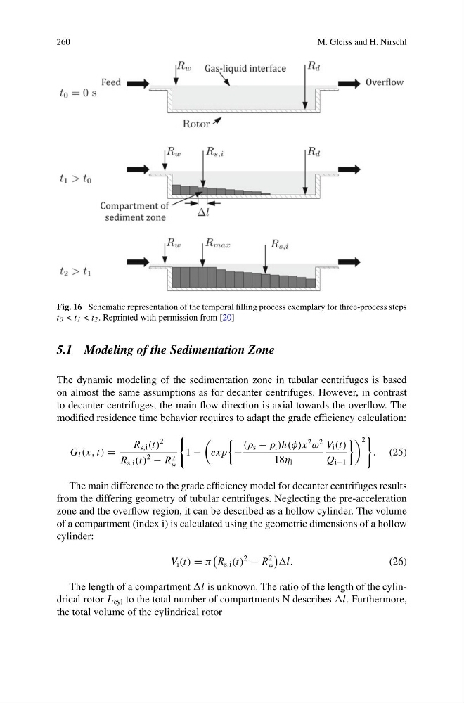
Fig. 16 Schematic representation of the temporal filling process exemplary for three-process steps
t 0 < t 1 < t 2 . Reprinted with permission from [20]
5.1 Modeling of the Sedimentation Zone
The dynamic modeling of the sedimentation zone in tubular centrifuges is based
on almost the same assumptions as for decanter centrifuges. However, in contrast
to decanter centrifuges, the main flow direction is axial towards the overflow. The
modified residence time behavior requires to adapt the grade efficiency calculation:
G i (x, t) =
R s,i (t)
2
R s,i (t)
2
− R 2
w
1 −
ex p
−
(ρ s − ρ l )h(φ)x
2
ω
2
18η l
V i (t)
Q i−1
2
. (25)
The main difference to the grade efficiency model for decanter centrifuges results
from the differing geometry of tubular centrifuges. Neglecting the pre-acceleration
zone and the overflow region, it can be described as a hollow cylinder. The volume
of a compartment (index i) is calculated using the geometric dimensions of a hollow
cylinder:
V i (t) = π
R s,i (t)
2
− R
2
w
l.
(26)
The length of a compartment l is unknown. The ratio of the length of the cylindrical rotor L cyl to the total number of compartments N describes l. Furthermore,
the total volume of the cylindrical rotor
M. Gleiss and H. Nirschl
Fig. 16 Schematic representation of the temporal filling process exemplary for three-process steps
t 0 < t 1 < t 2 . Reprinted with permission from [20]
5.1 Modeling of the Sedimentation Zone
The dynamic modeling of the sedimentation zone in tubular centrifuges is based
on almost the same assumptions as for decanter centrifuges. However, in contrast
to decanter centrifuges, the main flow direction is axial towards the overflow. The
modified residence time behavior requires to adapt the grade efficiency calculation:
G i (x, t) =
R s,i (t)
2
R s,i (t)
2
− R 2
w
1 −
ex p
−
(ρ s − ρ l )h(φ)x
2
ω
2
18η l
V i (t)
Q i−1
2
. (25)
The main difference to the grade efficiency model for decanter centrifuges results
from the differing geometry of tubular centrifuges. Neglecting the pre-acceleration
zone and the overflow region, it can be described as a hollow cylinder. The volume
of a compartment (index i) is calculated using the geometric dimensions of a hollow
cylinder:
V i (t) = π
R s,i (t)
2
− R
2
w
l.
(26)
The length of a compartment l is unknown. The ratio of the length of the cylindrical rotor L cyl to the total number of compartments N describes l. Furthermore,
the total volume of the cylindrical rotor