

7 Dynamic Simulation of Mechanical Fluid Separation in Solid …
257
volume fraction in the overflow is negligible in a wide range of 0.25 ≤ T ≤ 1.
A clear deviation from simulation and experiment is only detectable for T = 0.1.
For this setting, the sediment transport is inefficient and the machine fills almost
completely. As a result, only a small volume is available for the separation and the
solids volume fraction at the overflow increases due to the short residence time in
the apparatus.
The right-hand side in Fig. 12 exhibits the impact of transport efficiency on the
mean solids volume fraction φ c and the maximum solids volume fraction at the inner
wall of the drum φ c,max as a function of rotational speed. The comparison of the
results points out that there is only a small influence of the transport efficiency on
the solids volume fraction in the underflow. This results in only a slight shift of the
curves towards a larger solids volume fraction due to the rising sediment volume.
Another field of application for decanter centrifuges is the classification of finely
dispersed particles. The aim here is to adjust selectively the particle size of the
valuable product. For testing the applicability of dynamic modeling, finely dispersed
limestone is classified in a pilot decanter centrifuge. The following parameters serve
as simulation setup: Q = 0.5 m
3 h
−1 , φ in = 0.15 and n = 15 rpm.
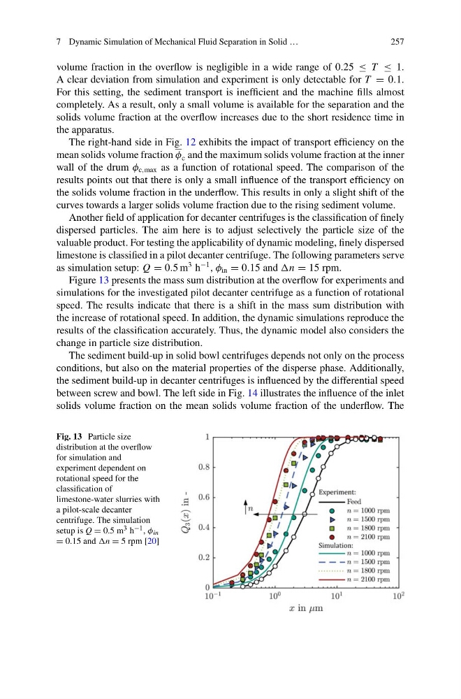
Figure 13 presents the mass sum distribution at the overflow for experiments and
simulations for the investigated pilot decanter centrifuge as a function of rotational
speed. The results indicate that there is a shift in the mass sum distribution with
the increase of rotational speed. In addition, the dynamic simulations reproduce the
results of the classification accurately. Thus, the dynamic model also considers the
change in particle size distribution.
The sediment build-up in solid bowl centrifuges depends not only on the process
conditions, but also on the material properties of the disperse phase. Additionally,
the sediment build-up in decanter centrifuges is influenced by the differential speed
between screw and bowl. The left side in Fig. 14 illustrates the influence of the inlet
solids volume fraction on the mean solids volume fraction of the underflow. The
Fig. 13 Particle size
distribution at the overflow
for simulation and
experiment dependent on
rotational speed for the
classification of
limestone-water slurries with
a pilot-scale decanter
centrifuge. The simulation
setup is Q = 0.5 m 3 h −1 , φ in
= 0.15 and n = 5 rpm [20]
257
volume fraction in the overflow is negligible in a wide range of 0.25 ≤ T ≤ 1.
A clear deviation from simulation and experiment is only detectable for T = 0.1.
For this setting, the sediment transport is inefficient and the machine fills almost
completely. As a result, only a small volume is available for the separation and the
solids volume fraction at the overflow increases due to the short residence time in
the apparatus.
The right-hand side in Fig. 12 exhibits the impact of transport efficiency on the
mean solids volume fraction φ c and the maximum solids volume fraction at the inner
wall of the drum φ c,max as a function of rotational speed. The comparison of the
results points out that there is only a small influence of the transport efficiency on
the solids volume fraction in the underflow. This results in only a slight shift of the
curves towards a larger solids volume fraction due to the rising sediment volume.
Another field of application for decanter centrifuges is the classification of finely
dispersed particles. The aim here is to adjust selectively the particle size of the
valuable product. For testing the applicability of dynamic modeling, finely dispersed
limestone is classified in a pilot decanter centrifuge. The following parameters serve
as simulation setup: Q = 0.5 m
3 h
−1 , φ in = 0.15 and n = 15 rpm.
Figure 13 presents the mass sum distribution at the overflow for experiments and
simulations for the investigated pilot decanter centrifuge as a function of rotational
speed. The results indicate that there is a shift in the mass sum distribution with
the increase of rotational speed. In addition, the dynamic simulations reproduce the
results of the classification accurately. Thus, the dynamic model also considers the
change in particle size distribution.
The sediment build-up in solid bowl centrifuges depends not only on the process
conditions, but also on the material properties of the disperse phase. Additionally,
the sediment build-up in decanter centrifuges is influenced by the differential speed
between screw and bowl. The left side in Fig. 14 illustrates the influence of the inlet
solids volume fraction on the mean solids volume fraction of the underflow. The
Fig. 13 Particle size
distribution at the overflow
for simulation and
experiment dependent on
rotational speed for the
classification of
limestone-water slurries with
a pilot-scale decanter
centrifuge. The simulation
setup is Q = 0.5 m 3 h −1 , φ in
= 0.15 and n = 5 rpm [20]