

210
G. Fragnière et al.
Table 2 Average velocity and position change for contact cases [12]
Contact case
Start velocity—crosswise velocity
Average velocity [m/s] Average change in position [m]
0.050–0.000
0.257 · v start
0.420 · d p
0.050–0.001
0.250 · v start
0.546 · d p
0.050–0.002
0.229 · v start
0.439 · d p
0.050–0.003
0.210 · v start
0.683 · d p
0.100–0.000
0.276 · v start
0.520 · d p
0.100–0.002
0.280 · v start
0.446 · d p
0.100–0.004
0.270 · v start
0.470 · d p
0.100–0.006
0.239 · v start
0.301 · d p
The absolute product particle velocity increases with rising grinding media starting velocity. The more angled the impact of the grinding beads is, the smaller is the
average acceleration of the product particles. No clear dependency can be detected
for the mean position change. Here significantly more variations need to be examined
and for the analysis of the flow in the gap another method is required, observing this
area with higher resolution.
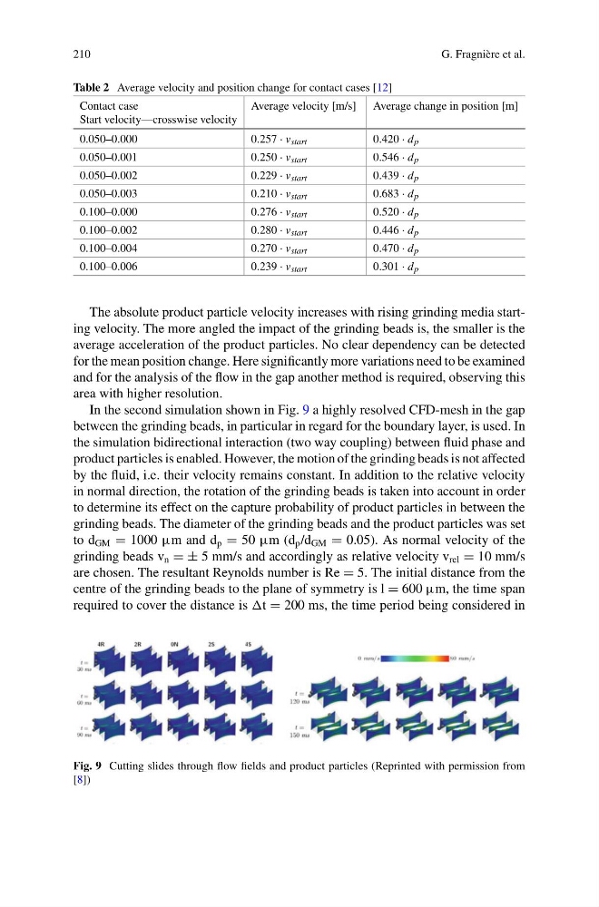
In the second simulation shown in Fig. 9 a highly resolved CFD-mesh in the gap
between the grinding beads, in particular in regard for the boundary layer, is used. In
the simulation bidirectional interaction (two way coupling) between fluid phase and
product particles is enabled. However, the motion of the grinding beads is not affected
by the fluid, i.e. their velocity remains constant. In addition to the relative velocity
in normal direction, the rotation of the grinding beads is taken into account in order
to determine its effect on the capture probability of product particles in between the
grinding beads. The diameter of the grinding beads and the product particles was set
to d GM = 1000 μm and d p = 50 μm (d p /d GM = 0.05). As normal velocity of the
grinding beads v n = ± 5 mm/s and accordingly as relative velocity v rel = 10 mm/s
are chosen. The resultant Reynolds number is Re = 5. The initial distance from the
centre of the grinding beads to the plane of symmetry is l = 600 μm, the time span
required to cover the distance is t = 200 ms, the time period being considered in
Fig. 9 Cutting slides through flow fields and product particles (Reprinted with permission from
[8])
G. Fragnière et al.
Table 2 Average velocity and position change for contact cases [12]
Contact case
Start velocity—crosswise velocity
Average velocity [m/s] Average change in position [m]
0.050–0.000
0.257 · v start
0.420 · d p
0.050–0.001
0.250 · v start
0.546 · d p
0.050–0.002
0.229 · v start
0.439 · d p
0.050–0.003
0.210 · v start
0.683 · d p
0.100–0.000
0.276 · v start
0.520 · d p
0.100–0.002
0.280 · v start
0.446 · d p
0.100–0.004
0.270 · v start
0.470 · d p
0.100–0.006
0.239 · v start
0.301 · d p
The absolute product particle velocity increases with rising grinding media starting velocity. The more angled the impact of the grinding beads is, the smaller is the
average acceleration of the product particles. No clear dependency can be detected
for the mean position change. Here significantly more variations need to be examined
and for the analysis of the flow in the gap another method is required, observing this
area with higher resolution.
In the second simulation shown in Fig. 9 a highly resolved CFD-mesh in the gap
between the grinding beads, in particular in regard for the boundary layer, is used. In
the simulation bidirectional interaction (two way coupling) between fluid phase and
product particles is enabled. However, the motion of the grinding beads is not affected
by the fluid, i.e. their velocity remains constant. In addition to the relative velocity
in normal direction, the rotation of the grinding beads is taken into account in order
to determine its effect on the capture probability of product particles in between the
grinding beads. The diameter of the grinding beads and the product particles was set
to d GM = 1000 μm and d p = 50 μm (d p /d GM = 0.05). As normal velocity of the
grinding beads v n = ± 5 mm/s and accordingly as relative velocity v rel = 10 mm/s
are chosen. The resultant Reynolds number is Re = 5. The initial distance from the
centre of the grinding beads to the plane of symmetry is l = 600 μm, the time span
required to cover the distance is t = 200 ms, the time period being considered in
Fig. 9 Cutting slides through flow fields and product particles (Reprinted with permission from
[8])