

208
G. Fragnière et al.
arranged. The distance of the grinding beads to the centre at the starting point is l =
750 μm. In Table 1 the resulting angle to the middle as well as the respective velocity
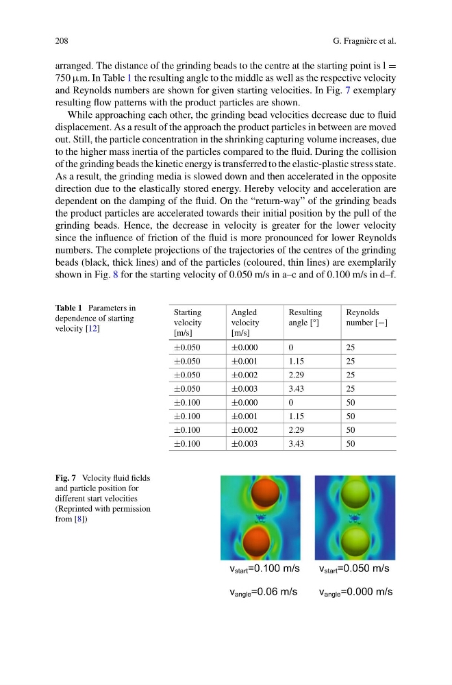
and Reynolds numbers are shown for given starting velocities. In Fig. 7 exemplary
resulting flow patterns with the product particles are shown.
While approaching each other, the grinding bead velocities decrease due to fluid
displacement. As a result of the approach the product particles in between are moved
out. Still, the particle concentration in the shrinking capturing volume increases, due
to the higher mass inertia of the particles compared to the fluid. During the collision
of the grinding beads the kinetic energy is transferred to the elastic-plastic stress state.
As a result, the grinding media is slowed down and then accelerated in the opposite
direction due to the elastically stored energy. Hereby velocity and acceleration are
dependent on the damping of the fluid. On the “return-way” of the grinding beads
the product particles are accelerated towards their initial position by the pull of the
grinding beads. Hence, the decrease in velocity is greater for the lower velocity
since the influence of friction of the fluid is more pronounced for lower Reynolds
numbers. The complete projections of the trajectories of the centres of the grinding
beads (black, thick lines) and of the particles (coloured, thin lines) are exemplarily
shown in Fig. 8 for the starting velocity of 0.050 m/s in a–c and of 0.100 m/s in d–f.
Table 1 Parameters in
dependence of starting
velocity [12]
Starting
velocity
[m/s]
Angled
velocity
[m/s]
Resulting
angle [°]
Reynolds
number [−]
±0.050
±0.000
0
25
±0.050
±0.001
1.15
25
±0.050
±0.002
2.29
25
±0.050
±0.003
3.43
25
±0.100
±0.000
0
50
±0.100
±0.001
1.15
50
±0.100
±0.002
2.29
50
±0.100
±0.003
3.43
50
Fig. 7 Velocity fluid fields
and particle position for
different start velocities
(Reprinted with permission
from [8])
v start =0.100 m/s
v angle =0.06 m/s
v start =0.050 m/s
v angle =0.000 m/s
G. Fragnière et al.
arranged. The distance of the grinding beads to the centre at the starting point is l =
750 μm. In Table 1 the resulting angle to the middle as well as the respective velocity
and Reynolds numbers are shown for given starting velocities. In Fig. 7 exemplary
resulting flow patterns with the product particles are shown.
While approaching each other, the grinding bead velocities decrease due to fluid
displacement. As a result of the approach the product particles in between are moved
out. Still, the particle concentration in the shrinking capturing volume increases, due
to the higher mass inertia of the particles compared to the fluid. During the collision
of the grinding beads the kinetic energy is transferred to the elastic-plastic stress state.
As a result, the grinding media is slowed down and then accelerated in the opposite
direction due to the elastically stored energy. Hereby velocity and acceleration are
dependent on the damping of the fluid. On the “return-way” of the grinding beads
the product particles are accelerated towards their initial position by the pull of the
grinding beads. Hence, the decrease in velocity is greater for the lower velocity
since the influence of friction of the fluid is more pronounced for lower Reynolds
numbers. The complete projections of the trajectories of the centres of the grinding
beads (black, thick lines) and of the particles (coloured, thin lines) are exemplarily
shown in Fig. 8 for the starting velocity of 0.050 m/s in a–c and of 0.100 m/s in d–f.
Table 1 Parameters in
dependence of starting
velocity [12]
Starting
velocity
[m/s]
Angled
velocity
[m/s]
Resulting
angle [°]
Reynolds
number [−]
±0.050
±0.000
0
25
±0.050
±0.001
1.15
25
±0.050
±0.002
2.29
25
±0.050
±0.003
3.43
25
±0.100
±0.000
0
50
±0.100
±0.001
1.15
50
±0.100
±0.002
2.29
50
±0.100
±0.003
3.43
50
Fig. 7 Velocity fluid fields
and particle position for
different start velocities
(Reprinted with permission
from [8])
v start =0.100 m/s
v angle =0.06 m/s
v start =0.050 m/s
v angle =0.000 m/s