

118
H. Rehage and M. Kind
WI
FIC
FIC
M M
TI
TI
TI TI
Pump 2
Pump 1
Outlet
Mixing Reactor
1
2
3
4
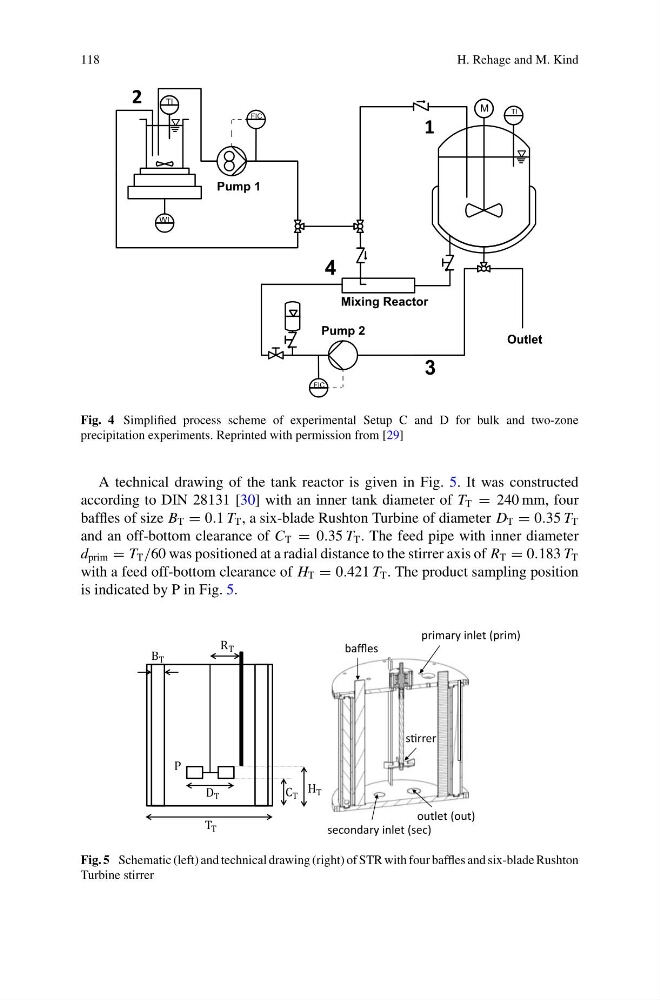
Fig. 4 Simplified process scheme of experimental Setup C and D for bulk and two-zone
precipitation experiments. Reprinted with permission from [29]
A technical drawing of the tank reactor is given in Fig. 5. It was constructed
according to DIN 28131 [30] with an inner tank diameter of T T = 240 mm, four
baffles of size B T = 0.1 T T , a six-blade Rushton Turbine of diameter D T = 0.35 T T
and an off-bottom clearance of C T = 0.35 T T . The feed pipe with inner diameter
d prim = T T /60 was positioned at a radial distance to the stirrer axis of R T = 0.183 T T
with a feed off-bottom clearance of H T = 0.421 T T . The product sampling position
is indicated by P in Fig. 5.
secondary inlet (sec)
outlet (out)
baffles
primary inlet (prim)
sƟrrer
Fig. 5 Schematic (left) and technical drawing (right) of STR with four baffles and six-blade Rushton
Turbine stirrer
H. Rehage and M. Kind
WI
FIC
FIC
M M
TI
TI
TI TI
Pump 2
Pump 1
Outlet
Mixing Reactor
1
2
3
4
Fig. 4 Simplified process scheme of experimental Setup C and D for bulk and two-zone
precipitation experiments. Reprinted with permission from [29]
A technical drawing of the tank reactor is given in Fig. 5. It was constructed
according to DIN 28131 [30] with an inner tank diameter of T T = 240 mm, four
baffles of size B T = 0.1 T T , a six-blade Rushton Turbine of diameter D T = 0.35 T T
and an off-bottom clearance of C T = 0.35 T T . The feed pipe with inner diameter
d prim = T T /60 was positioned at a radial distance to the stirrer axis of R T = 0.183 T T
with a feed off-bottom clearance of H T = 0.421 T T . The product sampling position
is indicated by P in Fig. 5.
secondary inlet (sec)
outlet (out)
baffles
primary inlet (prim)
sƟrrer
Fig. 5 Schematic (left) and technical drawing (right) of STR with four baffles and six-blade Rushton
Turbine stirrer