

74
3 Forced Vibration of Single Degree of Freedom System
From Eq. (3.14), we get
Y =
F 0
k
( 1 − η 2 ) 2 + ( 2 η ζ ) 2
Substituting the value of Y in Eq. (3.31), we get
F T 0 =
F 0
1 +
cω
k
2
( 1 − η 2 ) 2 + ( 2η ζ ) 2
(3.32)
Now
cω/k = cω/mp
2
= 2 ·
c
2m
ω
p 2 = 2 · n/ p · ω/ p = 2 η ζ
Therefore, Eq. (3.32) becomes
F T 0
F 0
=
1 + ( 2η ζ ) 2
( 1 − η 2 ) 2 + ( 2η ζ ) 2
(3.33)
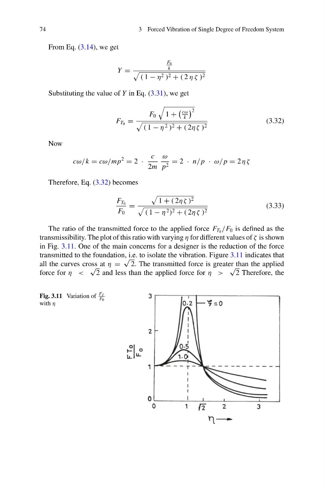
The ratio of the transmitted force to the applied force F T 0 /F 0 is defined as the
transmissibility. The plot of this ratio with varying η for different values of ζ is shown
in Fig. 3.11. One of the main concerns for a designer is the reduction of the force
transmitted to the foundation, i.e. to isolate the vibration. Figure 3.11 indicates that
all the curves cross at η =
√
2. The transmitted force is greater than the applied
force for η <
√
2 and less than the applied force for η >
√
2 Therefore, the
Fig. 3.11 Variation of
F T
F0
with η
3 Forced Vibration of Single Degree of Freedom System
From Eq. (3.14), we get
Y =
F 0
k
( 1 − η 2 ) 2 + ( 2 η ζ ) 2
Substituting the value of Y in Eq. (3.31), we get
F T 0 =
F 0
1 +
cω
k
2
( 1 − η 2 ) 2 + ( 2η ζ ) 2
(3.32)
Now
cω/k = cω/mp
2
= 2 ·
c
2m
ω
p 2 = 2 · n/ p · ω/ p = 2 η ζ
Therefore, Eq. (3.32) becomes
F T 0
F 0
=
1 + ( 2η ζ ) 2
( 1 − η 2 ) 2 + ( 2η ζ ) 2
(3.33)
The ratio of the transmitted force to the applied force F T 0 /F 0 is defined as the
transmissibility. The plot of this ratio with varying η for different values of ζ is shown
in Fig. 3.11. One of the main concerns for a designer is the reduction of the force
transmitted to the foundation, i.e. to isolate the vibration. Figure 3.11 indicates that
all the curves cross at η =
√
2. The transmitted force is greater than the applied
force for η <
√
2 and less than the applied force for η >
√
2 Therefore, the
Fig. 3.11 Variation of
F T
F0
with η