

Appendix A: The Stiffness Matrix
613
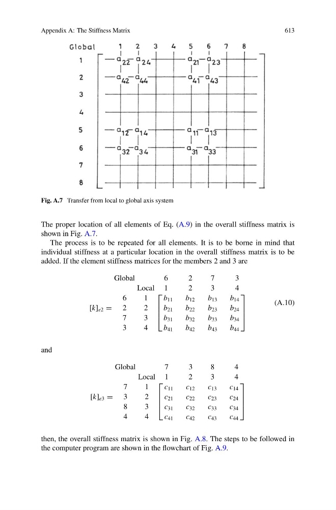
Fig. A.7 Transfer from local to global axis system
The proper location of all elements of Eq. (A.9) in the overall stiffness matrix is
shown in Fig. A.7.
The process is to be repeated for all elements. It is to be borne in mind that
individual stiffness at a particular location in the overall stiffness matrix is to be
added. If the element stiffness matrices for the members 2 and 3 are
Global
Local
6
1
[k] e2 = 2
2
7
3
3
4
6
1
⎡
⎢
⎢
⎣
b 11
b 21
b 31
b 41
2
2
b 12
b 22
b 32
b 42
7
3
b 13
b 23
b 33
b 43
3
4
b 14
b 24
b 34
b 44
⎤
⎥
⎥
⎦
(A.10)
and
Global
Local
7
1
[k] e3 = 3
2
8
3
4
4
7
1
⎡
⎢
⎢
⎣
c 11
c 21
c 31
c 41
3
2
c 12
c 22
c 32
c 42
8
3
c 13
c 23
c 33
c 43
4
4
c 14
c 24
c 34
c 44
⎤
⎥
⎥
⎦
then, the overall stiffness matrix is shown in Fig. A.8. The steps to be followed in
the computer program are shown in the flowchart of Fig. A.9.