

612
Appendix A: The Stiffness Matrix
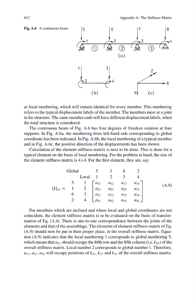
Fig. A.6 A continuous beam
as local numbering, which will remain identical for every member. This numbering
refers to the typical displacement labels of the member. The members meet at a joint
in the structure. The same member ends will have different displacement labels, when
the total structure is considered.
The continuous beam of Fig. A.6 has four degrees of freedom rotation at four
supports. In Fig. A.6a, the numbering from left-hand side corresponding to global
coordinate has been indicated. In Fig. A.6b, the local numbering of a typical member
and in Fig. A.6c, the positive direction of the displacements has been shown.
Calculation of the element stiffness matrix is next to be done. This is done for a
typical element on the basis of local numbering. For the problem at hand, the size of
the element stiffness matrix is 4×4. For the first element, they are, say
Global
Local
5
1
[k] e1 = 1
2
6
3
2
4
5
1
⎡
⎢
⎢
⎣
a 11
a 21
a 31
a 41
1
2
a 12
a 22
a 32
a 42
6
3
a 13
a 23
a 33
a 43
2
4
a 14
a 24
a 34
a 44
⎤
⎥
⎥
⎦
(A.9)
For members which are inclined and where local and global coordinates are not
coincident, the element stiffness matrix is to be evaluated on the basis of transformation of Eq. (A.4). There is one-to-one correspondence between the joints of the
elements and that of the assemblage. The elements of element stiffness matrix of Eq.
(A.9) should now be put in their proper place, in the overall stiffness matrix. Equation (A.9) indicates that the local numbering 1 corresponds to global numbering 5,
which means that a 11 should occupy the fifth row and the fifth column (i.e. k 55 ) of the
overall stiffness matrix. Local number 2 corresponds to global number 1. Therefore,
a 11 , a 21 , a 22 will occupy positions of k 51 , k 15 and k 11 of the overall stiffness matrix.