

12.6 Inplane Vibration of Plates
463
[M] e = ρ
t
12
⎡
⎢
⎢
⎢
⎢
⎢
⎢
⎢
⎣
2
0
2
Symmertical
1
0
2
0
1
0
2
1
0
1
0
2
0
1
0
1
0
2
⎤
⎥
⎥
⎥
⎥
⎥
⎥
⎥
⎦
(12.101)
12.6.2 Linear Rectangular Element
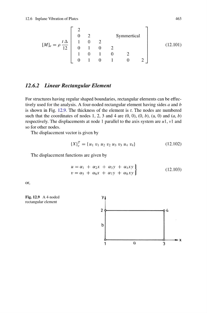
For structures having regular shaped boundaries, rectangular elements can be effectively used for the analysis. A four-noded rectangular element having sides a and b
is shown in Fig. 12.9. The thickness of the element is t. The nodes are numbered
such that the coordinates of nodes 1, 2, 3 and 4 are (0, 0), (0, b), (a, 0) and (a, b)
respectively. The displacements at node 1 parallel to the axis system are u1, v1 and
so for other nodes.
The displacement vector is given by
{X }
T
e = { u 1 v 1 u 2 v 2 u 3 v 3 u 4 v 4 }
(12.102)
The displacement functions are given by
u = α 1 + α 2 x + α 3 y + α 4 x y
v = α 5 + α 6 x + α 7 y + α 8 x y
(12.103)
or,
Fig. 12.9 A 4-noded
rectangular element
463
[M] e = ρ
t
12
⎡
⎢
⎢
⎢
⎢
⎢
⎢
⎢
⎣
2
0
2
Symmertical
1
0
2
0
1
0
2
1
0
1
0
2
0
1
0
1
0
2
⎤
⎥
⎥
⎥
⎥
⎥
⎥
⎥
⎦
(12.101)
12.6.2 Linear Rectangular Element
For structures having regular shaped boundaries, rectangular elements can be effectively used for the analysis. A four-noded rectangular element having sides a and b
is shown in Fig. 12.9. The thickness of the element is t. The nodes are numbered
such that the coordinates of nodes 1, 2, 3 and 4 are (0, 0), (0, b), (a, 0) and (a, b)
respectively. The displacements at node 1 parallel to the axis system are u1, v1 and
so for other nodes.
The displacement vector is given by
{X }
T
e = { u 1 v 1 u 2 v 2 u 3 v 3 u 4 v 4 }
(12.102)
The displacement functions are given by
u = α 1 + α 2 x + α 3 y + α 4 x y
v = α 5 + α 6 x + α 7 y + α 8 x y
(12.103)
or,
Fig. 12.9 A 4-noded
rectangular element