

10.5 Dynamic Stiffness Matrix for Flexure and …
409
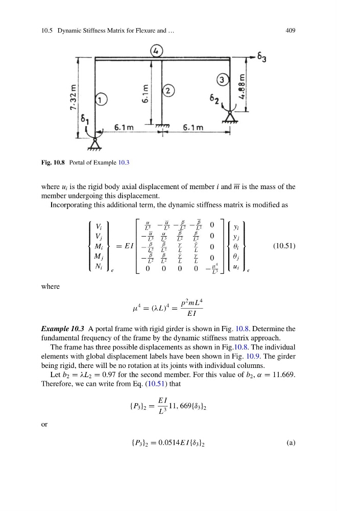
Fig. 10.8 Portal of Example 10.3
where u i is the rigid body axial displacement of member i and m is the mass of the
member undergoing this displacement.
Incorporating this additional term, the dynamic stiffness matrix is modified as
⎧
⎪ ⎪ ⎪ ⎪ ⎪ ⎨
⎪ ⎪ ⎪ ⎪ ⎪ ⎩
V i
V j
M i
M j
N i
⎫
⎪ ⎪ ⎪ ⎪ ⎪ ⎬
⎪ ⎪ ⎪ ⎪ ⎪ ⎭
e
= E I
⎡
⎢
⎢
⎢
⎢
⎢
⎢
⎣
α
L 3 −
α
L 3 −
β
L 2 −
β
L 2
0
−
α
L 3
α
L 3
β
L 2
β
L 2
0
−
β
L 2
β
L 2
γ
L
¯
γ
L
0
−
β
L 2
β
L 2
¯
γ
L
γ
L
0
0
0
0
0 −
μ
4
L 3
⎤
⎥
⎥
⎥
⎥
⎥
⎥
⎦
⎧
⎪ ⎪ ⎪ ⎪ ⎪ ⎨
⎪ ⎪ ⎪ ⎪ ⎪ ⎩
y i
y j
θ i
θ j
u i
⎫
⎪ ⎪ ⎪ ⎪ ⎪ ⎬
⎪ ⎪ ⎪ ⎪ ⎪ ⎭
e
(10.51)
where
μ
4
= (λL)
4
=
p
2 m L
4
E I
Example 10.3 A portal frame with rigid girder is shown in Fig. 10.8. Determine the
fundamental frequency of the frame by the dynamic stiffness matrix approach.
The frame has three possible displacements as shown in Fig.10.8. The individual
elements with global displacement labels have been shown in Fig. 10.9. The girder
being rigid, there will be no rotation at its joints with individual columns.
Let b 2 = λL 2 = 0.97 for the second member. For this value of b 2 , α = 11.669.
Therefore, we can write from Eq. (10.51) that
{P 3 } 2 =
E I
L 3 11, 669{δ 3 } 2
or
{P 3 } 2 = 0.0514E I {δ 3 } 2
(a)
409
Fig. 10.8 Portal of Example 10.3
where u i is the rigid body axial displacement of member i and m is the mass of the
member undergoing this displacement.
Incorporating this additional term, the dynamic stiffness matrix is modified as
⎧
⎪ ⎪ ⎪ ⎪ ⎪ ⎨
⎪ ⎪ ⎪ ⎪ ⎪ ⎩
V i
V j
M i
M j
N i
⎫
⎪ ⎪ ⎪ ⎪ ⎪ ⎬
⎪ ⎪ ⎪ ⎪ ⎪ ⎭
e
= E I
⎡
⎢
⎢
⎢
⎢
⎢
⎢
⎣
α
L 3 −
α
L 3 −
β
L 2 −
β
L 2
0
−
α
L 3
α
L 3
β
L 2
β
L 2
0
−
β
L 2
β
L 2
γ
L
¯
γ
L
0
−
β
L 2
β
L 2
¯
γ
L
γ
L
0
0
0
0
0 −
μ
4
L 3
⎤
⎥
⎥
⎥
⎥
⎥
⎥
⎦
⎧
⎪ ⎪ ⎪ ⎪ ⎪ ⎨
⎪ ⎪ ⎪ ⎪ ⎪ ⎩
y i
y j
θ i
θ j
u i
⎫
⎪ ⎪ ⎪ ⎪ ⎪ ⎬
⎪ ⎪ ⎪ ⎪ ⎪ ⎭
e
(10.51)
where
μ
4
= (λL)
4
=
p
2 m L
4
E I
Example 10.3 A portal frame with rigid girder is shown in Fig. 10.8. Determine the
fundamental frequency of the frame by the dynamic stiffness matrix approach.
The frame has three possible displacements as shown in Fig.10.8. The individual
elements with global displacement labels have been shown in Fig. 10.9. The girder
being rigid, there will be no rotation at its joints with individual columns.
Let b 2 = λL 2 = 0.97 for the second member. For this value of b 2 , α = 11.669.
Therefore, we can write from Eq. (10.51) that
{P 3 } 2 =
E I
L 3 11, 669{δ 3 } 2
or
{P 3 } 2 = 0.0514E I {δ 3 } 2
(a)