

320
8 Free Vibration Analysis of Continuous Systems
If the torsional spring is provided as the right-hand support, then
k 0 θ = −G J
∂θ
∂ x
(8.70)
One end of the shaft may have a disc of polar moment of inertia J 0 .
If the disc is placed on the left-hand end, then the end condition is
J 0
∂
2
θ
∂ t 2 = G J
∂θ
∂ x
(8.71)
If the disc is placed on the right-hand end, then the end condition is
J 0
∂
2
θ
∂ t 2 = −G J
∂θ
∂ x
(8.72)
The natural frequencies and mode shapes can be determined in the same way as
indicated in Art. 8.3.1.
In order to treat torsional vibrations of non-circular sections, the torque–twist
relation given by Eq. (8.65) is to be modified. It becomes
T = μG J
∂θ
∂ x
(8.73)
where μ is a factor depending on cross-sectional dimensions and the type of the
section. Further derivation for non-circular sections may be based on the relation
given by Eq. (8.73).
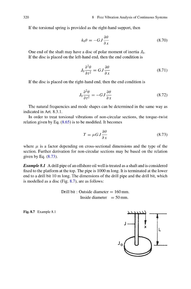
Example 8.1 A drill pipe of an offshore oil well is treated as a shaft and is considered
fixed to the platform at the top. The pipe is 1000 m long. It is terminated at the lower
end to a drill bit 10 m long. The dimensions of the drill pipe and the drill bit, which
is modelled as a disc (Fig. 8.7), are as follows:
Drill bit : Outside diameter = 160 mm.
Inside diameter = 50 mm.
Fig. 8.7 Example 8.1
8 Free Vibration Analysis of Continuous Systems
If the torsional spring is provided as the right-hand support, then
k 0 θ = −G J
∂θ
∂ x
(8.70)
One end of the shaft may have a disc of polar moment of inertia J 0 .
If the disc is placed on the left-hand end, then the end condition is
J 0
∂
2
θ
∂ t 2 = G J
∂θ
∂ x
(8.71)
If the disc is placed on the right-hand end, then the end condition is
J 0
∂
2
θ
∂ t 2 = −G J
∂θ
∂ x
(8.72)
The natural frequencies and mode shapes can be determined in the same way as
indicated in Art. 8.3.1.
In order to treat torsional vibrations of non-circular sections, the torque–twist
relation given by Eq. (8.65) is to be modified. It becomes
T = μG J
∂θ
∂ x
(8.73)
where μ is a factor depending on cross-sectional dimensions and the type of the
section. Further derivation for non-circular sections may be based on the relation
given by Eq. (8.73).
Example 8.1 A drill pipe of an offshore oil well is treated as a shaft and is considered
fixed to the platform at the top. The pipe is 1000 m long. It is terminated at the lower
end to a drill bit 10 m long. The dimensions of the drill pipe and the drill bit, which
is modelled as a disc (Fig. 8.7), are as follows:
Drill bit : Outside diameter = 160 mm.
Inside diameter = 50 mm.
Fig. 8.7 Example 8.1