

236
6 Free Vibration of Multiple Degrees of Freedom System
U =
1
2
K 1 θ
2
1 +
1
2
K 2 θ
2
2
U =
1
2
K 1 θ
2
1 +
1
2
K 2 n
2
θ
2
1
⎫
⎬
⎭
(6.122)
The equivalent stiffness of shaft 2 with reference to shaft 1 is n
2 k 2 .
The equivalent single shaft system is shown in Fig. 6.20b. Thus, the rule to be
followed for the geared system is as follows: multiply all stiffness and inertias of
the geared shaft by n
2 , where n is the speed ratio of the geared shaft to the reference
shaft.
In dealing with multi-speed systems, it is convenient to transform the system into
one of the constant speeds using suitable equivalent masses and stiffness coefficients.
6.19 Branched Systems
Branched systems are frequently encountered in engineering. Their examples include
ship shafting installations, either as twin-screw or as twin-engine systems, drive shaft
and the differential of an automobile.
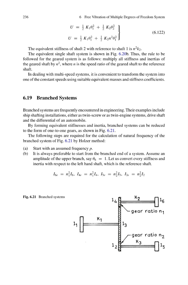
By forming equivalent stiffnesses and inertia, branched systems can be reduced
to the form of one-to-one gears, as shown in Fig. 6.21.
The following steps are required for the calculation of natural frequency of the
branched system of Fig. 6.21 by Holzer method:
(a) Start with an assumed frequency p.
(b) It is always preferable to start from the branched end of a system. Assume an
amplitude of the upper branch, say θ 6 = 1. Let us convert every stiffness and
inertia with respect to the left hand shaft, which is the reference shaft.
I 6e = n
2
1 I 6 , I 4e = n
2
1 I 4 , I 5e = n
2
2 I 5 , I 2e = n
2
2 I 2
Fig. 6.21 Branched systems
6 Free Vibration of Multiple Degrees of Freedom System
U =
1
2
K 1 θ
2
1 +
1
2
K 2 θ
2
2
U =
1
2
K 1 θ
2
1 +
1
2
K 2 n
2
θ
2
1
⎫
⎬
⎭
(6.122)
The equivalent stiffness of shaft 2 with reference to shaft 1 is n
2 k 2 .
The equivalent single shaft system is shown in Fig. 6.20b. Thus, the rule to be
followed for the geared system is as follows: multiply all stiffness and inertias of
the geared shaft by n
2 , where n is the speed ratio of the geared shaft to the reference
shaft.
In dealing with multi-speed systems, it is convenient to transform the system into
one of the constant speeds using suitable equivalent masses and stiffness coefficients.
6.19 Branched Systems
Branched systems are frequently encountered in engineering. Their examples include
ship shafting installations, either as twin-screw or as twin-engine systems, drive shaft
and the differential of an automobile.
By forming equivalent stiffnesses and inertia, branched systems can be reduced
to the form of one-to-one gears, as shown in Fig. 6.21.
The following steps are required for the calculation of natural frequency of the
branched system of Fig. 6.21 by Holzer method:
(a) Start with an assumed frequency p.
(b) It is always preferable to start from the branched end of a system. Assume an
amplitude of the upper branch, say θ 6 = 1. Let us convert every stiffness and
inertia with respect to the left hand shaft, which is the reference shaft.
I 6e = n
2
1 I 6 , I 4e = n
2
1 I 4 , I 5e = n
2
2 I 5 , I 2e = n
2
2 I 2
Fig. 6.21 Branched systems