

212
6 Free Vibration of Multiple Degrees of Freedom System
Let us consider that the beam is having lumped masses, and the sections in between
the masses are massless. Figure 6.15 shows a typical section. Let us approach the
problem in a general manner, by incorporating the shear deformation and rotary
inertia effects. These effects have been discussed in details in Chap. 8, but here, we
adopt certain equations derived in that chapter. For free vibration of the beam, the
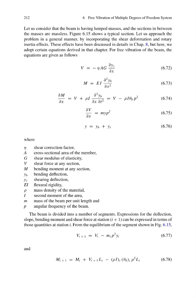
equations are given as follows
V = − η AG
∂ y s
∂ x
(6.72)
M = E I
∂
2 y b
∂ x 2
(6.73)
∂ M
∂ x
= V + ρ I
∂
3 y b
∂ x ∂t 2 = V − ρ I θ b p
2
(6.74)
∂ V
∂ x
= myp
2
(6.75)
y = y b + y s
(6.76)
where
η
shear correction factor,
A
cross-sectional area of the member,
G
shear modulus of elasticity,
V
shear force at any section,
M bending moment at any section,
y b bending deflection,
y s shearing deflection,
EI flexural rigidity,
ρ
mass density of the material,
I
second moment of the area,
m
mass of the beam per unit length and
p
angular frequency of the beam.
The beam is divided into a number of segments. Expressions for the deflection,
slope, bending moment and shear force at station (i + 1) can be expressed in terms of
those quantities at station i. From the equilibrium of the segment shown in Fig. 6.15,
V i + 1 = V i − m i p
2 y i
(6.77)
and
M i + 1 = M i + V i + 1 L i − (ρ I ) i ( θ b ) i p
2 L i
(6.78)
6 Free Vibration of Multiple Degrees of Freedom System
Let us consider that the beam is having lumped masses, and the sections in between
the masses are massless. Figure 6.15 shows a typical section. Let us approach the
problem in a general manner, by incorporating the shear deformation and rotary
inertia effects. These effects have been discussed in details in Chap. 8, but here, we
adopt certain equations derived in that chapter. For free vibration of the beam, the
equations are given as follows
V = − η AG
∂ y s
∂ x
(6.72)
M = E I
∂
2 y b
∂ x 2
(6.73)
∂ M
∂ x
= V + ρ I
∂
3 y b
∂ x ∂t 2 = V − ρ I θ b p
2
(6.74)
∂ V
∂ x
= myp
2
(6.75)
y = y b + y s
(6.76)
where
η
shear correction factor,
A
cross-sectional area of the member,
G
shear modulus of elasticity,
V
shear force at any section,
M bending moment at any section,
y b bending deflection,
y s shearing deflection,
EI flexural rigidity,
ρ
mass density of the material,
I
second moment of the area,
m
mass of the beam per unit length and
p
angular frequency of the beam.
The beam is divided into a number of segments. Expressions for the deflection,
slope, bending moment and shear force at station (i + 1) can be expressed in terms of
those quantities at station i. From the equilibrium of the segment shown in Fig. 6.15,
V i + 1 = V i − m i p
2 y i
(6.77)
and
M i + 1 = M i + V i + 1 L i − (ρ I ) i ( θ b ) i p
2 L i
(6.78)