

6.10 Transfer Matrix Method
205
6.10 Transfer Matrix Method
We start by introducing the concepts of the state vector. A state vector at a station i
of an elastic system is a column matrix, the elements of which are the displacements
and internal forces at point i. For the case of a spring–mass system, the state vector
is defined as
{Z } i =
x i
N i
=
x
N
i
(6.59)
where x i is the linear displacement of the spring and N i is the corresponding spring
force.
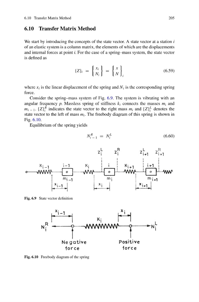
Consider the spring–mass system of Fig. 6.9. The system is vibrating with an
angular frequency p. Massless spring of stiffness k i connects the masses m i and
m i − 1 . {Z }
R
i indicates the state vector to the right mass m i and {Z }
L
i denotes the
state vector to the left of mass m i . The freebody diagram of this spring is shown in
Fig. 6.10.
Equilibrium of the spring yields
N
R
i − 1 = N
L
i
(6.60)
Fig. 6.9 State vector definition
Fig. 6.10 Freebody diagram of the spring
205
6.10 Transfer Matrix Method
We start by introducing the concepts of the state vector. A state vector at a station i
of an elastic system is a column matrix, the elements of which are the displacements
and internal forces at point i. For the case of a spring–mass system, the state vector
is defined as
{Z } i =
x i
N i
=
x
N
i
(6.59)
where x i is the linear displacement of the spring and N i is the corresponding spring
force.
Consider the spring–mass system of Fig. 6.9. The system is vibrating with an
angular frequency p. Massless spring of stiffness k i connects the masses m i and
m i − 1 . {Z }
R
i indicates the state vector to the right mass m i and {Z }
L
i denotes the
state vector to the left of mass m i . The freebody diagram of this spring is shown in
Fig. 6.10.
Equilibrium of the spring yields
N
R
i − 1 = N
L
i
(6.60)
Fig. 6.9 State vector definition
Fig. 6.10 Freebody diagram of the spring