

3.2 Thermodynamic Aspects of Gas Hydrates
69
isothermally, the system reaches another triple-phase curve of oil–clathrate–gas (oil
newly forms). Above this pressure, all the excess gas is liquefied, and the system
consists of two phases of an excess oil and the clathrate. At an initial temperature
that is higher than that of the upper quadruple point, the system initially consists of
two phases of liquid water and gas at a low pressure. As the pressure is increased
isothermally, the system reaches the triple-phase curve of oil–water–gas (oil newly
forms). Above this pressure, all the gas in the system is liquefied, and the system
consists of two phases of oil and liquid water.
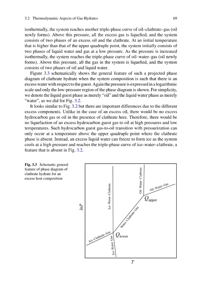
Figure 3.3 schematically shows the general feature of such a projected phase
diagram of clathrate hydrate when the system composition is such that there is an
excess water with respect to the guest. Again the pressure is expressed in a logarithmic
scale and only the low-pressure region of the phase diagram is shown. For simplicity,
we denote the liquid guest phase as merely “oil” and the liquid water phase as merely
“water”, as we did for Fig. 3.2.
It looks similar to Fig. 3.2 but there are important differences due to the different
excess components. Unlike in the case of an excess oil, there would be no excess
hydrocarbon gas or oil in the presence of clathrate here. Therefore, there would be
no liquefaction of an excess hydrocarbon guest gas to oil at high pressures and low
temperatures. Such hydrocarbon guest gas-to-oil transition with pressurization can
only occur at a temperature above the upper quadruple point where the clathrate
phase is absent. Instead, an excess liquid water can freeze to form ice as the system
cools at a high pressure and reaches the triple-phase curve of ice–water–clathrate, a
feature that is absent in Fig. 3.2.
Fig. 3.3 Schematic general
feature of phase diagram of
clathrate hydrate for an
excess host composition
Ice–Water–Clathrate
Oil–Water–Clathrate
T
lnP
Q lower
Q upper
69
isothermally, the system reaches another triple-phase curve of oil–clathrate–gas (oil
newly forms). Above this pressure, all the excess gas is liquefied, and the system
consists of two phases of an excess oil and the clathrate. At an initial temperature
that is higher than that of the upper quadruple point, the system initially consists of
two phases of liquid water and gas at a low pressure. As the pressure is increased
isothermally, the system reaches the triple-phase curve of oil–water–gas (oil newly
forms). Above this pressure, all the gas in the system is liquefied, and the system
consists of two phases of oil and liquid water.
Figure 3.3 schematically shows the general feature of such a projected phase
diagram of clathrate hydrate when the system composition is such that there is an
excess water with respect to the guest. Again the pressure is expressed in a logarithmic
scale and only the low-pressure region of the phase diagram is shown. For simplicity,
we denote the liquid guest phase as merely “oil” and the liquid water phase as merely
“water”, as we did for Fig. 3.2.
It looks similar to Fig. 3.2 but there are important differences due to the different
excess components. Unlike in the case of an excess oil, there would be no excess
hydrocarbon gas or oil in the presence of clathrate here. Therefore, there would be
no liquefaction of an excess hydrocarbon guest gas to oil at high pressures and low
temperatures. Such hydrocarbon guest gas-to-oil transition with pressurization can
only occur at a temperature above the upper quadruple point where the clathrate
phase is absent. Instead, an excess liquid water can freeze to form ice as the system
cools at a high pressure and reaches the triple-phase curve of ice–water–clathrate, a
feature that is absent in Fig. 3.2.
Fig. 3.3 Schematic general
feature of phase diagram of
clathrate hydrate for an
excess host composition
Ice–Water–Clathrate
Oil–Water–Clathrate
T
lnP
Q lower
Q upper