

46
A. K. Choudhary and R. Jain
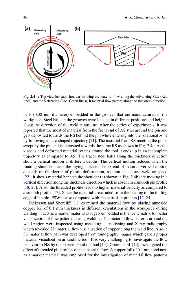
Fig. 2.4 a Top view beneath shoulder showing the material flow along the Advancing Side (Red
lines) and the Retreating Side (Green lines), b material flow pattern along the thickness direction
balls (0.38 mm diameter) embedded in the grooves that are manufactured in the
workpiece. Steel balls in the grooves were located in different positions and heights
along the direction of the weld centreline. After the series of experiments, it was
reported that the most of material from the front end of AS stirs around the pin and
gets deposited towards the RS behind the pin while entering into the rotational zone
by following an arc-shaped trajectory [21]. The material from RS meeting the pin is
swept by the pin and is deposited towards the same RS as shown in Fig. 2.4a. As the
viscous and deformed material rotates around the tool it ends up in an incomplete
trajectory as compared to AS. The tracer steel balls along the thickness direction
show a vertical motion at different depths. The vertical motion reduces when the
rotating shoulder meets the faying surface. The extend of material vertical motion
depends on the degree of plastic deformation, rotation speed, and welding speed
[22]. It shows material beneath the shoulder (as shown in Fig. 2.4b) are moving in a
vertical direction along the thickness direction which is absent in a smooth pin profile
[18, 23]. Also, the threaded profile leads to higher material velocity as compared to
a smooth profile [17]. Since the material is extruded from the leading to the trailing
edge of the pin, FSW is also compared with the extrusion process [12, 24].
Dickerson and Shercliff [11] examined the material flow by placing annealed
copper foil of 0.1 mm thickness in different orientations in the workpiece during
welding. It acts as a marker material as it gets embedded in the weld matrix for better
visualization of flow patterns during welding. The material flow patterns around the
weld region were inspected using metallurgical polishing and X-ray radiography
which revealed 2D material flow visualization of copper along the weld line. Also, a
3D material flow path was developed from tomography images which gave a proper
material visualization around the tool. It is very challenging to investigate the flow
behavior in NZ by the experimental method [14]. Guerra et al. [13] investigated the
effect of threaded pin profiles on the material flow. A copper foil of 0.1 mm thickness
as a marker material was employed for the investigation of material flow patterns
A. K. Choudhary and R. Jain
Fig. 2.4 a Top view beneath shoulder showing the material flow along the Advancing Side (Red
lines) and the Retreating Side (Green lines), b material flow pattern along the thickness direction
balls (0.38 mm diameter) embedded in the grooves that are manufactured in the
workpiece. Steel balls in the grooves were located in different positions and heights
along the direction of the weld centreline. After the series of experiments, it was
reported that the most of material from the front end of AS stirs around the pin and
gets deposited towards the RS behind the pin while entering into the rotational zone
by following an arc-shaped trajectory [21]. The material from RS meeting the pin is
swept by the pin and is deposited towards the same RS as shown in Fig. 2.4a. As the
viscous and deformed material rotates around the tool it ends up in an incomplete
trajectory as compared to AS. The tracer steel balls along the thickness direction
show a vertical motion at different depths. The vertical motion reduces when the
rotating shoulder meets the faying surface. The extend of material vertical motion
depends on the degree of plastic deformation, rotation speed, and welding speed
[22]. It shows material beneath the shoulder (as shown in Fig. 2.4b) are moving in a
vertical direction along the thickness direction which is absent in a smooth pin profile
[18, 23]. Also, the threaded profile leads to higher material velocity as compared to
a smooth profile [17]. Since the material is extruded from the leading to the trailing
edge of the pin, FSW is also compared with the extrusion process [12, 24].
Dickerson and Shercliff [11] examined the material flow by placing annealed
copper foil of 0.1 mm thickness in different orientations in the workpiece during
welding. It acts as a marker material as it gets embedded in the weld matrix for better
visualization of flow patterns during welding. The material flow patterns around the
weld region were inspected using metallurgical polishing and X-ray radiography
which revealed 2D material flow visualization of copper along the weld line. Also, a
3D material flow path was developed from tomography images which gave a proper
material visualization around the tool. It is very challenging to investigate the flow
behavior in NZ by the experimental method [14]. Guerra et al. [13] investigated the
effect of threaded pin profiles on the material flow. A copper foil of 0.1 mm thickness
as a marker material was employed for the investigation of material flow patterns