

402
S. Papaefthymiou
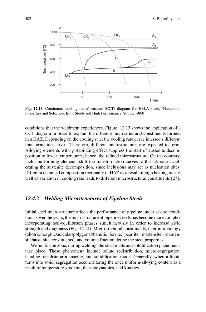
Fig. 12.13 Continuous cooling transformation (CCT) diagram for HSLA steels (Handbook,
Properties and Selection: Irons Steels and High Performance Alloys, 1990)
conditions that the weldment experiences. Figure. 12.13 shows the application of a
CCT diagram in order to explain the different microstructural constituents formed
in a HAZ. Depending on the cooling rate, the cooling rate curve intersects different
transformation curves. Therefore, different microstructures are expected to form.
Alloying elements with γ stabilizing effect suppress the start of austenite decomposition to lower temperatures, hence, the refined microstructure. On the contrary,
inclusion forming elements shift the transformation curves to the left side accelerating the austenite decomposition, since inclusions may act as nucleation sites.
Different chemical composition regionally in HAZ as a result of high heating rate as
well as variation in cooling rate leads to different microstructural constituents [27].
12.4.2 Welding Microstructures of Pipeline Steels
Initial steel microstructure affects the performance of pipeline under severe conditions. Over the years, the microstructure of pipeline steels has become more complex
incorporating non-equilibrium phases simultaneously in order to increase yield
strength and toughness (Fig. 12.14). Microstructural constituents, their morphology
(allotriomorphic/acicular/polygonal/bainitic ferrite, pearlite, martensite—martensite/austenite constituents), and volume fraction define the steel properties.
Within fusion zone, during welding, the steel melts and solidification phenomena
take place. These phenomena include solute redistribution, micro-segregation,
banding, dendrite-arm spacing, and solidification mode. Generally, when a liquid
turns into solid, segregation occurs altering the once uniform-alloying content as a
result of temperature gradient, thermodynamics, and kinetics.
S. Papaefthymiou
Fig. 12.13 Continuous cooling transformation (CCT) diagram for HSLA steels (Handbook,
Properties and Selection: Irons Steels and High Performance Alloys, 1990)
conditions that the weldment experiences. Figure. 12.13 shows the application of a
CCT diagram in order to explain the different microstructural constituents formed
in a HAZ. Depending on the cooling rate, the cooling rate curve intersects different
transformation curves. Therefore, different microstructures are expected to form.
Alloying elements with γ stabilizing effect suppress the start of austenite decomposition to lower temperatures, hence, the refined microstructure. On the contrary,
inclusion forming elements shift the transformation curves to the left side accelerating the austenite decomposition, since inclusions may act as nucleation sites.
Different chemical composition regionally in HAZ as a result of high heating rate as
well as variation in cooling rate leads to different microstructural constituents [27].
12.4.2 Welding Microstructures of Pipeline Steels
Initial steel microstructure affects the performance of pipeline under severe conditions. Over the years, the microstructure of pipeline steels has become more complex
incorporating non-equilibrium phases simultaneously in order to increase yield
strength and toughness (Fig. 12.14). Microstructural constituents, their morphology
(allotriomorphic/acicular/polygonal/bainitic ferrite, pearlite, martensite—martensite/austenite constituents), and volume fraction define the steel properties.
Within fusion zone, during welding, the steel melts and solidification phenomena
take place. These phenomena include solute redistribution, micro-segregation,
banding, dendrite-arm spacing, and solidification mode. Generally, when a liquid
turns into solid, segregation occurs altering the once uniform-alloying content as a
result of temperature gradient, thermodynamics, and kinetics.