

12 Industrial Pipeline Welding
393
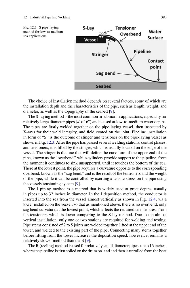
Fig. 12.3 S pipe-laying
method for low-to-medium
sea applications
The choice of installation method depends on several factors, some of which are
the installation depth and the characteristics of the pipe, such as length, weight, and
diameter, as well as the topography of the seabed [9].
The S-laying method is the most common in submarine applications, especially for
relatively large diameter pipes (d > 16
) and is used at low-to-medium water depths.
The pipes are firstly welded together on the pipe-laying vessel, then inspected by
X-rays for their weld integrity, and field coated on the joint. Pipeline installation
in form of “S” is the outcome of stinger and tensioner on the pipe-laying vessel as
shown in Fig. 12.3. After the pipe has passed several welding stations, control phases,
and tensioners, it is lifted by the stinger, which is usually located on the edge of the
vessel. The stinger is the one that will define the curvature of the upper end of the
pipe, known as the “overbend,” while cylinders provide support to the pipeline, from
the moment it continues to sink unsupported, until it touches the bottom of the sea.
There at the lowest point, the pipe acquires a curvature opposite to the corresponding
overbend, known as the “sag bend,” and is the result of the tensioners and the weight
of the pipe, while it can be controlled by exerting a tensile stress on the pipe using
the vessels tensioning system [9].
The J piping method is a method that is widely used at great depths, usually
in pipes up to 32 inches in diameter. In the J deposition method, the conductor is
inserted into the sea from the vessel almost vertically as shown in Fig. 12.4, via a
tower installed on the vessel, so that as mentioned above, there is no overbend, only
sag bend curvature at the lowest point, which affects the required tensile stress from
the tensioners which is lower comparing to the S-lay method. Due to the almost
vertical installation, only one or two stations are required for welding and testing.
Pipe stems consisted of 2 to 5 joints are welded together, lifted at the upper end of the
tower, and welded to the existing part of the pipe. Connecting many stems together
before lifting from the tower increases the deposition speed; however, it remains a
relatively slower method than the S [9].
The R (reeling) method is used for relatively small diameter pipes, up to 16 inches,
where the pipeline is first coiled on the drum on land and then is unrolled from the boat
393
Fig. 12.3 S pipe-laying
method for low-to-medium
sea applications
The choice of installation method depends on several factors, some of which are
the installation depth and the characteristics of the pipe, such as length, weight, and
diameter, as well as the topography of the seabed [9].
The S-laying method is the most common in submarine applications, especially for
relatively large diameter pipes (d > 16
) and is used at low-to-medium water depths.
The pipes are firstly welded together on the pipe-laying vessel, then inspected by
X-rays for their weld integrity, and field coated on the joint. Pipeline installation
in form of “S” is the outcome of stinger and tensioner on the pipe-laying vessel as
shown in Fig. 12.3. After the pipe has passed several welding stations, control phases,
and tensioners, it is lifted by the stinger, which is usually located on the edge of the
vessel. The stinger is the one that will define the curvature of the upper end of the
pipe, known as the “overbend,” while cylinders provide support to the pipeline, from
the moment it continues to sink unsupported, until it touches the bottom of the sea.
There at the lowest point, the pipe acquires a curvature opposite to the corresponding
overbend, known as the “sag bend,” and is the result of the tensioners and the weight
of the pipe, while it can be controlled by exerting a tensile stress on the pipe using
the vessels tensioning system [9].
The J piping method is a method that is widely used at great depths, usually
in pipes up to 32 inches in diameter. In the J deposition method, the conductor is
inserted into the sea from the vessel almost vertically as shown in Fig. 12.4, via a
tower installed on the vessel, so that as mentioned above, there is no overbend, only
sag bend curvature at the lowest point, which affects the required tensile stress from
the tensioners which is lower comparing to the S-lay method. Due to the almost
vertical installation, only one or two stations are required for welding and testing.
Pipe stems consisted of 2 to 5 joints are welded together, lifted at the upper end of the
tower, and welded to the existing part of the pipe. Connecting many stems together
before lifting from the tower increases the deposition speed; however, it remains a
relatively slower method than the S [9].
The R (reeling) method is used for relatively small diameter pipes, up to 16 inches,
where the pipeline is first coiled on the drum on land and then is unrolled from the boat