

16
S. K. Das et al.
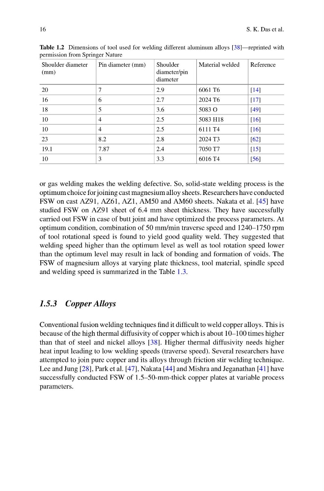
Table 1.2 Dimensions of tool used for welding different aluminum alloys [38]—reprinted with
permission from Springer Nature
Shoulder diameter
(mm)
Pin diameter (mm)
Shoulder
diameter/pin
diameter
Material welded
Reference
20
7
2.9
6061 T6
[14]
16
6
2.7
2024 T6
[17]
18
5
3.6
5083 O
[49]
10
4
2.5
5083 H18
[16]
10
4
2.5
6111 T4
[16]
23
8.2
2.8
2024 T3
[62]
19.1
7.87
2.4
7050 T7
[15]
10
3
3.3
6016 T4
[56]
or gas welding makes the welding defective. So, solid-state welding process is the
optimum choice for joining cast magnesium alloy sheets. Researchers have conducted
FSW on cast AZ91, AZ61, AZ1, AM50 and AM60 sheets. Nakata et al. [45] have
studied FSW on AZ91 sheet of 6.4 mm sheet thickness. They have successfully
carried out FSW in case of butt joint and have optimized the process parameters. At
optimum condition, combination of 50 mm/min traverse speed and 1240–1750 rpm
of tool rotational speed is found to yield good quality weld. They suggested that
welding speed higher than the optimum level as well as tool rotation speed lower
than the optimum level may result in lack of bonding and formation of voids. The
FSW of magnesium alloys at varying plate thickness, tool material, spindle speed
and welding speed is summarized in the Table 1.3.
1.5.3 Copper Alloys
Conventional fusion welding techniques find it difficult to weld copper alloys. This is
because of the high thermal diffusivity of copper which is about 10–100 times higher
than that of steel and nickel alloys [38]. Higher thermal diffusivity needs higher
heat input leading to low welding speeds (traverse speed). Several researchers have
attempted to join pure copper and its alloys through friction stir welding technique.
Lee and Jung [28], Park et al. [47], Nakata [44] and Mishra and Jeganathan [41] have
successfully conducted FSW of 1.5–50-mm-thick copper plates at variable process
parameters.
S. K. Das et al.
Table 1.2 Dimensions of tool used for welding different aluminum alloys [38]—reprinted with
permission from Springer Nature
Shoulder diameter
(mm)
Pin diameter (mm)
Shoulder
diameter/pin
diameter
Material welded
Reference
20
7
2.9
6061 T6
[14]
16
6
2.7
2024 T6
[17]
18
5
3.6
5083 O
[49]
10
4
2.5
5083 H18
[16]
10
4
2.5
6111 T4
[16]
23
8.2
2.8
2024 T3
[62]
19.1
7.87
2.4
7050 T7
[15]
10
3
3.3
6016 T4
[56]
or gas welding makes the welding defective. So, solid-state welding process is the
optimum choice for joining cast magnesium alloy sheets. Researchers have conducted
FSW on cast AZ91, AZ61, AZ1, AM50 and AM60 sheets. Nakata et al. [45] have
studied FSW on AZ91 sheet of 6.4 mm sheet thickness. They have successfully
carried out FSW in case of butt joint and have optimized the process parameters. At
optimum condition, combination of 50 mm/min traverse speed and 1240–1750 rpm
of tool rotational speed is found to yield good quality weld. They suggested that
welding speed higher than the optimum level as well as tool rotation speed lower
than the optimum level may result in lack of bonding and formation of voids. The
FSW of magnesium alloys at varying plate thickness, tool material, spindle speed
and welding speed is summarized in the Table 1.3.
1.5.3 Copper Alloys
Conventional fusion welding techniques find it difficult to weld copper alloys. This is
because of the high thermal diffusivity of copper which is about 10–100 times higher
than that of steel and nickel alloys [38]. Higher thermal diffusivity needs higher
heat input leading to low welding speeds (traverse speed). Several researchers have
attempted to join pure copper and its alloys through friction stir welding technique.
Lee and Jung [28], Park et al. [47], Nakata [44] and Mishra and Jeganathan [41] have
successfully conducted FSW of 1.5–50-mm-thick copper plates at variable process
parameters.