

152
P. Sarkar et al.
parameters that play a vital role in creating a channel in FSC are C and geometry of
the tool. The influence of various parameters that control the FSC process is discussed
briefly below:
Clearance between shoulder and workpiece surface, (C): Deposition of the
extracted material from the NZ at the top of the channel is needed to close the channel
roof. Thus, minimum C must be maintained. Higher C leads to open channels,
whereas very low value closes the path of the channel.
Tool rotational speed, (ω): Heat generation in FSC is directly proportional to ω. In
order to obtain a continuous channel, material should not be too softened, and thus
ω is restricted to a reasonably smaller value than that is used in FSW.
Tool traverse speed, (v): v also influences heat generation. For faster v, lesser would
be the quantity of heat generation, because of insufficient contact time of the pin
with the workpiece.
Tool geometry: The pin geometry governs the material removal from the base of the
workpiece. The material at the base of the plate is flown upward due to the thread
orientation of the pin. Again, use of spiral striate on the shoulder helps in moving the
material away from the shoulder. For a plain and smooth shoulder (i.e., not scrolled
or with nostriate), the material taken out by the threaded pin is settled down beneath
the shoulder, i.e., at the gap.
The FSC parameters cannot be directly assigned from one aluminium alloy to
another. For different grades of the same metal, the process parameters vary to give
a better-quality channel.
4.6 Evolution of FSC Process
From its invention, the FSC process, because of its huge potential to replace the
conventional techniques to create cooling channels and of the various advantages
of this process, researchers started working on this field to modify and develop the
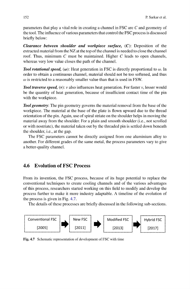
process further to make it more industry adaptable. A timeline of the evolution of
the process is given in Fig. 4.7.
The details of these processes are briefly discussed in the following sub-sections.
ConvenƟonal FSC
[2005]
New FSC
[2011]
Modified FSC
[2013]
Hybrid FSC
[2017]
Fig. 4.7 Schematic representation of development of FSC with time
P. Sarkar et al.
parameters that play a vital role in creating a channel in FSC are C and geometry of
the tool. The influence of various parameters that control the FSC process is discussed
briefly below:
Clearance between shoulder and workpiece surface, (C): Deposition of the
extracted material from the NZ at the top of the channel is needed to close the channel
roof. Thus, minimum C must be maintained. Higher C leads to open channels,
whereas very low value closes the path of the channel.
Tool rotational speed, (ω): Heat generation in FSC is directly proportional to ω. In
order to obtain a continuous channel, material should not be too softened, and thus
ω is restricted to a reasonably smaller value than that is used in FSW.
Tool traverse speed, (v): v also influences heat generation. For faster v, lesser would
be the quantity of heat generation, because of insufficient contact time of the pin
with the workpiece.
Tool geometry: The pin geometry governs the material removal from the base of the
workpiece. The material at the base of the plate is flown upward due to the thread
orientation of the pin. Again, use of spiral striate on the shoulder helps in moving the
material away from the shoulder. For a plain and smooth shoulder (i.e., not scrolled
or with nostriate), the material taken out by the threaded pin is settled down beneath
the shoulder, i.e., at the gap.
The FSC parameters cannot be directly assigned from one aluminium alloy to
another. For different grades of the same metal, the process parameters vary to give
a better-quality channel.
4.6 Evolution of FSC Process
From its invention, the FSC process, because of its huge potential to replace the
conventional techniques to create cooling channels and of the various advantages
of this process, researchers started working on this field to modify and develop the
process further to make it more industry adaptable. A timeline of the evolution of
the process is given in Fig. 4.7.
The details of these processes are briefly discussed in the following sub-sections.
ConvenƟonal FSC
[2005]
New FSC
[2011]
Modified FSC
[2013]
Hybrid FSC
[2017]
Fig. 4.7 Schematic representation of development of FSC with time