

1 Friction Stir Welding
3
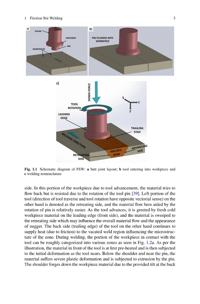
Fig. 1.1 Schematic diagram of FSW: a butt joint layout; b tool entering into workpiece and
c welding nomenclature
side. In this portion of the workpiece due to tool advancement, the material tries to
flow back but is resisted due to the rotation of the tool pin [39]. Left portion of the
tool (direction of tool traverse and tool rotation have opposite vectorial sense) on the
other hand is denoted as the retreating side, and the material flow here aided by the
rotation of pin is relatively easier. As the tool advances, it is greeted by fresh cold
workpiece material on the leading edge (front side), and the material is sweeped to
the retreating side which may influence the overall material flow and the appearance
of nugget. The back side (trailing edge) of the tool on the other hand continues to
supply heat (due to friction) to the vacated weld region influencing the microstructure of the zone. During welding, the portion of the workpiece in contact with the
tool can be roughly categorized into various zones as seen in Fig. 1.2a. As per the
illustration, the material in front of the tool is at first pre-heated and is then subjected
to the initial deformation as the tool nears. Below the shoulder and near the pin, the
material suffers severe plastic deformation and is subjected to extrusion by the pin.
The shoulder forges down the workpiece material due to the provided tilt at the back
3
Fig. 1.1 Schematic diagram of FSW: a butt joint layout; b tool entering into workpiece and
c welding nomenclature
side. In this portion of the workpiece due to tool advancement, the material tries to
flow back but is resisted due to the rotation of the tool pin [39]. Left portion of the
tool (direction of tool traverse and tool rotation have opposite vectorial sense) on the
other hand is denoted as the retreating side, and the material flow here aided by the
rotation of pin is relatively easier. As the tool advances, it is greeted by fresh cold
workpiece material on the leading edge (front side), and the material is sweeped to
the retreating side which may influence the overall material flow and the appearance
of nugget. The back side (trailing edge) of the tool on the other hand continues to
supply heat (due to friction) to the vacated weld region influencing the microstructure of the zone. During welding, the portion of the workpiece in contact with the
tool can be roughly categorized into various zones as seen in Fig. 1.2a. As per the
illustration, the material in front of the tool is at first pre-heated and is then subjected
to the initial deformation as the tool nears. Below the shoulder and near the pin, the
material suffers severe plastic deformation and is subjected to extrusion by the pin.
The shoulder forges down the workpiece material due to the provided tilt at the back