

3 Modeling of Friction Stir Welding Processes
111
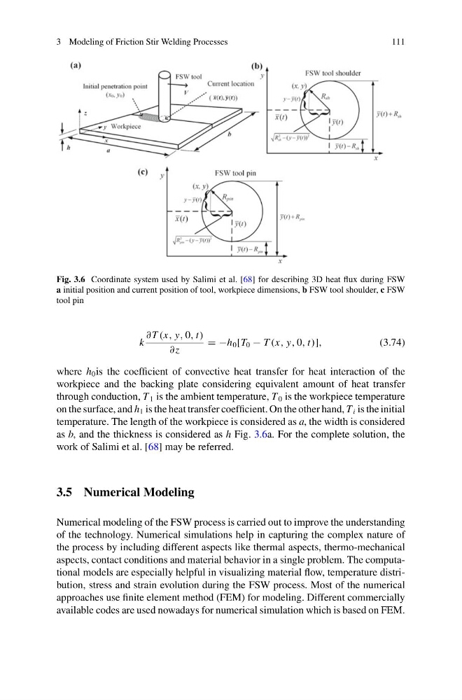
Fig. 3.6 Coordinate system used by Salimi et al. [68] for describing 3D heat flux during FSW
a initial position and current position of tool, workpiece dimensions, b FSW tool shoulder, c FSW
tool pin
k
∂ T (x, y, 0, t)
∂z
= −h 0 [T 0 − T (x, y, 0, t)],
(3.74)
where h 0 is the coefficient of convective heat transfer for heat interaction of the
workpiece and the backing plate considering equivalent amount of heat transfer
through conduction, T 1 is the ambient temperature, T 0 is the workpiece temperature
on the surface, and h 1 is the heat transfer coefficient. On the other hand, T i is the initial
temperature. The length of the workpiece is considered as a, the width is considered
as b, and the thickness is considered as h Fig. 3.6a. For the complete solution, the
work of Salimi et al. [68] may be referred.
3.5 Numerical Modeling
Numerical modeling of the FSW process is carried out to improve the understanding
of the technology. Numerical simulations help in capturing the complex nature of
the process by including different aspects like thermal aspects, thermo-mechanical
aspects, contact conditions and material behavior in a single problem. The computational models are especially helpful in visualizing material flow, temperature distribution, stress and strain evolution during the FSW process. Most of the numerical
approaches use finite element method (FEM) for modeling. Different commercially
available codes are used nowadays for numerical simulation which is based on FEM.
111
Fig. 3.6 Coordinate system used by Salimi et al. [68] for describing 3D heat flux during FSW
a initial position and current position of tool, workpiece dimensions, b FSW tool shoulder, c FSW
tool pin
k
∂ T (x, y, 0, t)
∂z
= −h 0 [T 0 − T (x, y, 0, t)],
(3.74)
where h 0 is the coefficient of convective heat transfer for heat interaction of the
workpiece and the backing plate considering equivalent amount of heat transfer
through conduction, T 1 is the ambient temperature, T 0 is the workpiece temperature
on the surface, and h 1 is the heat transfer coefficient. On the other hand, T i is the initial
temperature. The length of the workpiece is considered as a, the width is considered
as b, and the thickness is considered as h Fig. 3.6a. For the complete solution, the
work of Salimi et al. [68] may be referred.
3.5 Numerical Modeling
Numerical modeling of the FSW process is carried out to improve the understanding
of the technology. Numerical simulations help in capturing the complex nature of
the process by including different aspects like thermal aspects, thermo-mechanical
aspects, contact conditions and material behavior in a single problem. The computational models are especially helpful in visualizing material flow, temperature distribution, stress and strain evolution during the FSW process. Most of the numerical
approaches use finite element method (FEM) for modeling. Different commercially
available codes are used nowadays for numerical simulation which is based on FEM.