

increase of the impurity (neon) content results in a smooth reduction of the plasma
flux to the target and propagation of the detachment front towards the X-point
[51]. The reason for this is the progressive accumulation of the impurity in the
cold, virtually non-radiative divertor region that expands gradually. This effect plays
the role of negative feedback and prevents the development of thermal bifurcation.
We also notice that even the simulations with advanced 2D edge plasma transport
codes often show only qualitative agreement with the experimental data.
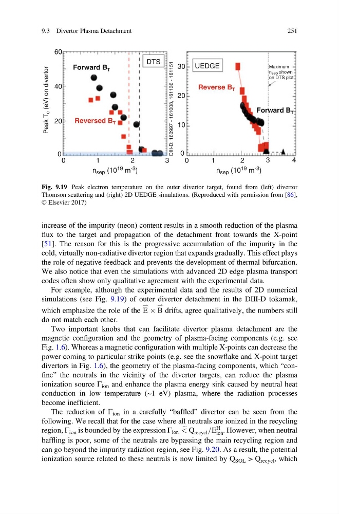
For example, although the experimental data and the results of 2D numerical
simulations (see Fig. 9.19) of outer divertor detachment in the DIII-D tokamak,
which emphasize the role of the E
! Â B
!
drifts, agree qualitatively, the numbers still
do not match each other.
Two important knobs that can facilitate divertor plasma detachment are the
magnetic configuration and the geometry of plasma-facing components (e.g. see
Fig. 1.6). Whereas a magnetic configuration with multiple X-points can decrease the
power coming to particular strike points (e.g. see the snowflake and X-point target
divertors in Fig. 1.6), the geometry of the plasma-facing components, which “confine” the neutrals in the vicinity of the divertor targets, can reduce the plasma
ionization source Γ ion and enhance the plasma energy sink caused by neutral heat
conduction in low temperature (~1 eV) plasma, where the radiation processes
become inefficient.
The reduction of Γ ion in a carefully “baffled” divertor can be seen from the
following. We recall that for the case where all neutrals are ionized in the recycling
region, Γ ion is bounded by the expression Γ ion e
< Q recycl =E
H
ion . However, when neutral
baffling is poor, some of the neutrals are bypassing the main recycling region and
can go beyond the impurity radiation region, see Fig. 9.20. As a result, the potential
ionization source related to these neutrals is now limited by Q SOL > Q recycl , which
60
40
Peak T
e (eV) on divertor
20
10
0
30
DTS
DIII-D: 160997 - 161008, 161136 - 161151
Forward B T
Forward B T
Reverse B T
Reversed B T
UEDGE
20
0
0
1
2
n sep (10 19 m -3 )
n sep (10 19 m -3 )
3
0
1
2
Maximum
nsep shown
on DTS plot
3
4
Fig. 9.19 Peak electron temperature on the outer divertor target, found from (left) divertor
Thomson scattering and (right) 2D UEDGE simulations. (Reproduced with permission from [86],
© Elsevier 2017)
9.3 Divertor Plasma Detachment
251
flux to the target and propagation of the detachment front towards the X-point
[51]. The reason for this is the progressive accumulation of the impurity in the
cold, virtually non-radiative divertor region that expands gradually. This effect plays
the role of negative feedback and prevents the development of thermal bifurcation.
We also notice that even the simulations with advanced 2D edge plasma transport
codes often show only qualitative agreement with the experimental data.
For example, although the experimental data and the results of 2D numerical
simulations (see Fig. 9.19) of outer divertor detachment in the DIII-D tokamak,
which emphasize the role of the E
! Â B
!
drifts, agree qualitatively, the numbers still
do not match each other.
Two important knobs that can facilitate divertor plasma detachment are the
magnetic configuration and the geometry of plasma-facing components (e.g. see
Fig. 1.6). Whereas a magnetic configuration with multiple X-points can decrease the
power coming to particular strike points (e.g. see the snowflake and X-point target
divertors in Fig. 1.6), the geometry of the plasma-facing components, which “confine” the neutrals in the vicinity of the divertor targets, can reduce the plasma
ionization source Γ ion and enhance the plasma energy sink caused by neutral heat
conduction in low temperature (~1 eV) plasma, where the radiation processes
become inefficient.
The reduction of Γ ion in a carefully “baffled” divertor can be seen from the
following. We recall that for the case where all neutrals are ionized in the recycling
region, Γ ion is bounded by the expression Γ ion e
< Q recycl =E
H
ion . However, when neutral
baffling is poor, some of the neutrals are bypassing the main recycling region and
can go beyond the impurity radiation region, see Fig. 9.20. As a result, the potential
ionization source related to these neutrals is now limited by Q SOL > Q recycl , which
60
40
Peak T
e (eV) on divertor
20
10
0
30
DTS
DIII-D: 160997 - 161008, 161136 - 161151
Forward B T
Forward B T
Reverse B T
Reversed B T
UEDGE
20
0
0
1
2
n sep (10 19 m -3 )
n sep (10 19 m -3 )
3
0
1
2
Maximum
nsep shown
on DTS plot
3
4
Fig. 9.19 Peak electron temperature on the outer divertor target, found from (left) divertor
Thomson scattering and (right) 2D UEDGE simulations. (Reproduced with permission from [86],
© Elsevier 2017)
9.3 Divertor Plasma Detachment
251